A city made of coloured pixels
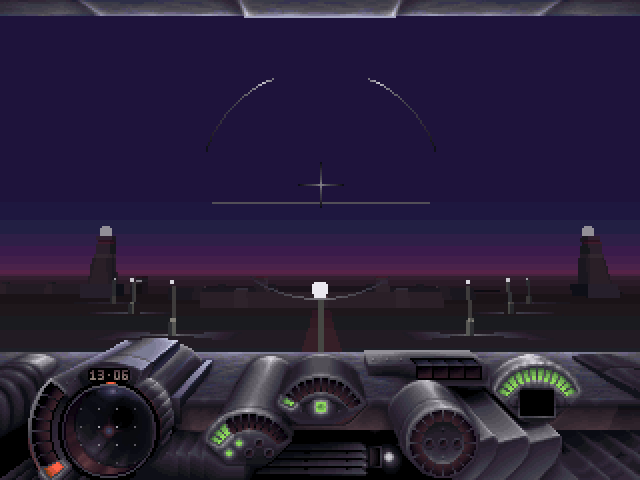
Fly low over Delphi and the buildings emerge from purple darkness. Streetlights pick out the roads, roofs catch a little light, and the fountain in Kismet Square reflects its lamps in rippling water. Much of the pleasure of taking Darker apart has been finding out how little machinery it takes to produce those effects.
Darker uses a software renderer. The CPU transforms the geometry, decides what overlaps what, and writes a colour index into each pixel. VGA displays the resulting image. Buildings get their surfaces from coloured polygons and gradients; a few carefully chosen palette ramps do much of the work of giving the city its character.
We will follow the 1995 retail renderer from map cells to the finished frame, using the code and assets recovered from the executable. The native rendering examples come from Darker C++, our reconstruction of the game.
The minimum vocabulary
A vertex is a point in three dimensions. Connect vertices into a polygon and you have a flat surface: a wall, a wing or one piece of a roof. A model groups those surfaces into an object. To draw it, the engine transforms its points into the camera’s coordinate system, projects them onto the screen, and fills the resulting two-dimensional polygons. That last operation is rasterisation.
Darker also draws lines, small circular discs, and sprites: little bitmap pictures used for smoke, fire and instruments. A beacon’s glowing top can be a disc while its supporting tower is made of polygons. A smooth-looking cylinder can be a small number of polygons with different brightness values across them.
The normal display is 320 × 240 pixels, or 76,800 colour indices. Each pixel stores one byte, selecting one of 256 palette entries. A palette entry supplies the red, green and blue values displayed for that index. Drawing a wall means filling its screen area with those byte-sized indices.
The distinction between a colour index and a colour is central to everything that follows. Darker arranges its palette into colour ramps, then does much of its shading by changing the index within a ramp.
Follow one frame
Most of the city is irrelevant to any one frame. The renderer starts by choosing nearby map cells, rejects models outside the view, puts the survivors in drawing order, and executes their drawing commands. Expensive work is left until the candidate list is small.
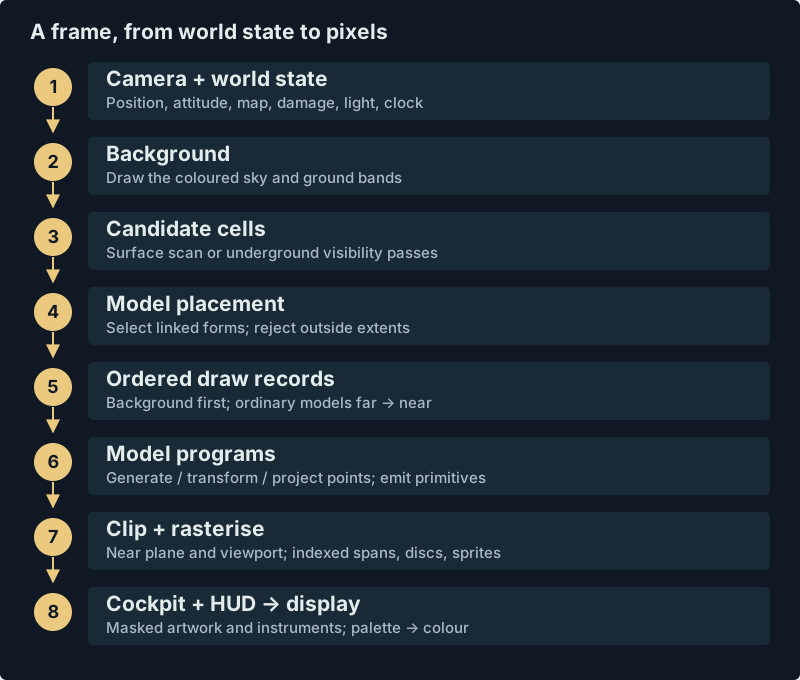
The important boundaries are:
- World state: where the camera and moving objects are, which map is active, which buildings are damaged, and how much power the beacons have.
- Visibility and placement: which model instances might be visible, which version of each model to use, and where its origin lies relative to the camera.
- Drawing: execute each model’s program, generate points, clip its primitives and write palette indices.
- Composition: combine that view with the cockpit, instruments, radar, targeting marks and messages; present it through the active palette.
The world has three main geometry banks: Delphi, Halon, and the underground sections. A bank supplies a directory of city types, a directory of moving-object models, and shared model data. Underground scenes use their own visibility search and sorting adjustments, which we will come to shortly.
Source: scene assembly and drawing.
From map cells to model instances
A city map is a 128 × 128 grid. Its stored type bytes identify what occupies each cell. Runtime setup expands those into cells containing a type and a mutable state byte. An empty cell needs no building model; an occupied cell refers to the bank’s type directory.
Each occupied cell places a model—a hangar, tower, road marking or tunnel segment—at an offset within its tile. The grid makes finding the nearby scenery cheap, while the models supply the shapes and heights. Moving craft have independent positions and orientations.
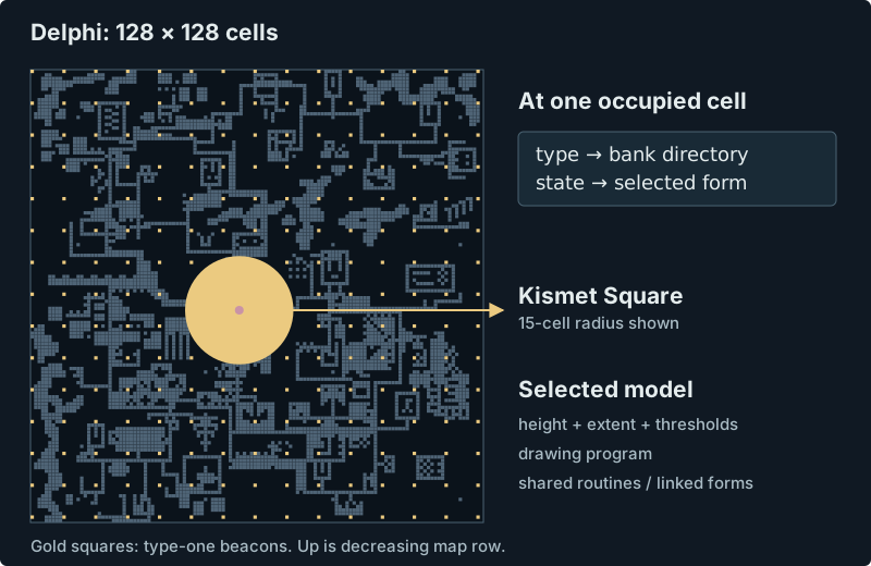
A city-type record supplies a model reference, fractional offsets within its tile, placement/collision information, and a variant limit. The selected model header supplies its height, extent and distance thresholds. Its first two words can also link to an alternate definition and a damaged definition. The renderer selects a definition before it starts drawing.
Destroying a building changes its cell state. On the next frame, the renderer follows the damaged-definition link and draws the replacement: a collapsed roof or a lower, broken silhouette, authored as another model. Several building types can share that replacement.
The same state byte has several jobs across the city. For a building it can select damage or an alternate form; for an animated object it can select parameters; for a beacon it holds the current light level. The type tells the engine how to interpret it.
Collision volumes accompany the visible models. Their placement explains some otherwise puzzling targeting behaviour: the vulnerable volume of certain office buildings is tucked inside the entrance, so a missile has to fly through the doorway to hit it. The full model inspector can overlay these volumes on the geometry.
Sources: bank decoding, linked model states.
The models are little programs
Darker’s models contain drawing bytecode. An instruction can change one coordinate, negate another, emit a point, draw a polygon, test a viewing direction, call a subroutine, or jump somewhere else in the model pool. Drawing a model means running a small program.
The interpreter keeps three coordinate components, called A, B and C in our analysis. It can reuse components from the preceding point, which makes symmetry cheap. For example, a rectangle can be described like this:
set C = 0, A = −64, B = −64; emit vertex 0
negate A;                   emit vertex 1
negate B;                   emit vertex 2
negate A;                   emit vertex 3
draw quad using vertices 0, 1, 2, 3
The first coordinate instruction takes one opcode and three 16-bit operands. Each subsequent negate-and-emit instruction takes one byte. Those four vertices need ten bytes of coordinate commands, compared with 24 bytes for four explicit triples, followed by the polygon’s colour and vertex indices.
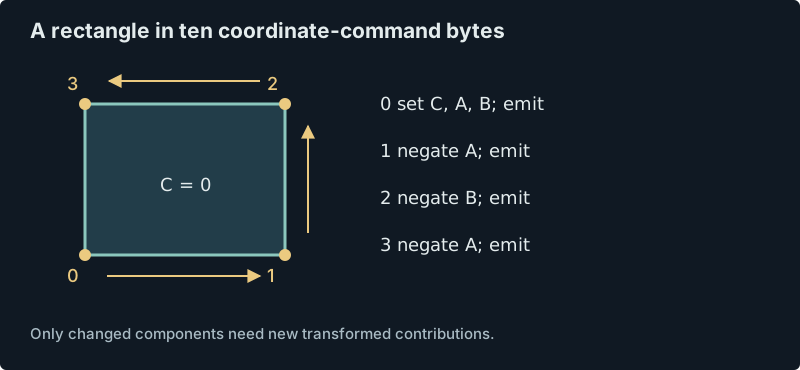
There is a useful saving at runtime too. A transformed point is a sum of three contributions: A multiplied by one camera-basis vector, B by another, and C by a third. The interpreter caches those contributions. Changing A requires three new multiplications; it can keep the products for B and C. Negating A simply negates its cached values. The rectangle above gets three of its four corners through sign changes and additions.
Relative calls let different models share drawing routines, while vertex-cursor commands reuse working storage. Conditional commands skip groups of faces according to viewing direction. This gives the model author control over drawing order: a group that should be behind another from one side can be handled differently when viewed from the other side.
Some of the retail drawing instructions
| Opcode | Operation |
|---|---|
8E |
Set C, A and B; emit a vertex. |
91 |
Set A and B, retain C; emit. |
73 / 76 / 79 |
Negate C / A / B; emit. |
02 / 03 |
Flat triangle / quadrilateral. |
0E / 0F / 11 |
Gouraud triangle / quadrilateral / counted polygon. |
16 |
Test projected facing and conditionally skip commands. |
1A |
Test distance and conditionally skip commands. |
1E / 22 |
Draw a line / screen-space disc. |
32 / 35 / 38 |
Set interpolation, save an anchor, emit an interpolated point. |
3B |
Set C from an animation parameter. |
3E / 4D / 0D |
Relative call / jump / return. |
The executable dispatches these through its FCxx and FExx paths. Some opcodes enter shared instruction sequences partway through, reusing the tail of another command’s implementation.
Sources: model interpreter, coordinate encoding.
Moving the world into the camera
Imagine the camera as the origin of a new set of axes: right, down, and forward. Subtract the camera’s position from a point in the world, then rotate that relative position by the camera’s attitude. The result tells us how far sideways, vertically and forward the point lies in the view.
In conventional mathematical notation:
camera_point = camera_rotation × (world_point − camera_position)
An independently rotating aircraft also needs its local-to-world rotation. Darker composes that with the camera basis. The static city has no need for a fresh object rotation at every cell.
Perspective then makes distant objects smaller. For a camera-space point (X, Y, Z), the familiar idealised projection is:
screen_x = centre_x + focal_length × X / Z
screen_y = centre_y + focal_length × Y / Z
Darker’s focal length is 256 pixels. The implementation keeps fractional bits in the X and Y numerators, divides by the whole depth word, and truncates the signed result towards zero to obtain a screen coordinate.
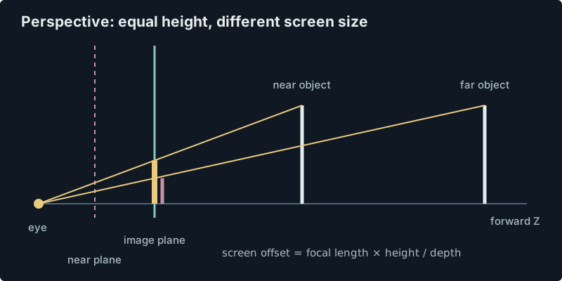
At 320 × 240, that focal length corresponds to approximately 64.0° horizontal and 50.2° vertical field of view for the full screen. The cockpit uses a shorter window into the world, so it shows less vertically: the normal Caero view is 168 rows, placed eight rows below the top; the Skimma view is 180 rows.
Fractions without floating point
Fixed point means storing fractions with an agreed scale. A world position word has 256 units per map cell, and movement retains an additional fractional byte. The camera setup multiplies the position word by four and takes the top two bits of that byte, producing coordinates in 1/1024-cell units. It trades some movement precision for enough whole bits to cover the visible neighbourhood.
Angles wrap around a 16-bit turn: 65,536 units bring you back to the same direction. The renderer looks up sine and cosine in a 1,024-entry signed table, so its effective angular step is about 0.352°. Camera setup selects an entry with (angle + 15) >> 6, wrapping the addition to 16 bits. Near zero, angles 0–48 select entry zero and 49–112 select entry one. The view stays still through each interval, then steps to the next orientation. At high resolution those small steps become quite conspicuous.
The sine table has a small asymmetry too: its positive peak is 32766, while its negative peak is −32767. We kept its original values when reconstructing the renderer, along with the intermediate truncations and fractional carries. Those details helped explain individual misplaced pixels in comparisons with the DOS game.
An unusually revealing shared byte
The coordinate interpreter’s A and B vertical contributions share a fractional byte at FCD3. Set A and its whole part goes into A’s cache while its fraction goes into the shared byte. Set B next and B replaces that fraction. Emitting a vertex sums both whole parts but includes the shared fraction only once. Reversing the two setters can therefore change the result, even though the final A and B coordinates are identical.
The interpolation commands used by gates save an anchor point, then emit points between that anchor and the current position. In the direct drawing path, a coordinate read reaches into an adjacent instruction. Its BA opcode byte becomes the fractional part of the vertical coordinate, adding 186/256 of a camera-coordinate unit. This small accidental offset also survives in the reconstruction.
Sources: camera placement, cached projection, native projection comparisons.
Choosing what is worth drawing
The surface renderer searches a neighbourhood with a radius of 15 map cells. An integer circle stepper generates row spans. Heading normally selects half of that neighbourhood; steep upward or downward views use the full circle. The centre row is treated specially and remains complete. This produces a candidate list for the more precise tests that follow.
Each candidate then undergoes placement and an extent-based camera-space rejection. The model’s extent allows it to survive when its origin is outside the view but part of its geometry might still be visible. The same classification chooses the cheaper direct projection path or the more careful near-clipping path.
Moving aircraft, vehicles, projectiles and effect emitters have a separate coordinate-window admission test before joining the scene. Each model’s header supplies distance thresholds for simplifying its appearance: Gouraud commands fall back to flat shading, and a sufficiently distant moving model becomes a single point.
The coordinate range also limits how far the search can extend. Placement doubles signed horizontal offsets into another 16-bit word. At roughly sixteen cells along an axis, those values can wrap, putting distant scenery on the wrong side of the camera. Extending the radius requires wider intermediate coordinates as well as changes to the search and shading tables.
Underground uses a different search
A tunnel is assembled from model-bearing map cells. Its search starts with the containing cell, proceeds along cardinal directions up to eight cells, then performs a series of diagonal and outward passes. Acceptance of one model sets a visibility bit used by neighbouring cells. Empty cardinal cells stop their ray; some visibility state persists between frames.
The visit order matters because later cells consult those bits. Reproducing the traversal meant following both the sequence of visits and the state carried over from the previous frame. The accepted models then enter the usual placement, ordering and polygon stages.
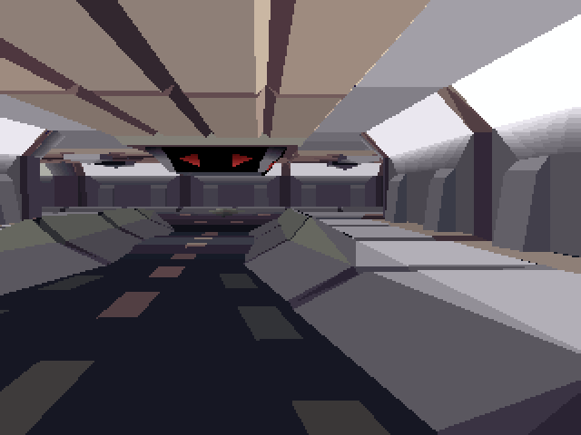
Sources: surface traversal, underground traversal and ordering.
Paint the far objects first
Draw a distant building first, then draw a nearer building over it. Where they overlap, the nearer one replaces the earlier pixels. This is the painter’s algorithm, and it makes drawing order responsible for visibility throughout Darker’s world renderer.
There are two levels of order. Between models, records are visited from farther to nearer. Inside a model, its drawing program determines which primitives come first. Facing tests skip hidden groups of geometry, and the polygon fillers reject faces whose projected vertices wind in the back-facing direction. Looking at the opposite side of a face reverses that clockwise or anticlockwise order, providing a cheap way to decide which side faces the camera.
The sorting key is a distance estimate based on the magnitudes of horizontal offsets and camera altitude, adjusted by the model’s extent. The engine inserts draw records into a binary tree using that key, then visits them in order. Background-marked city types go into a separate last-in-first-out list and draw first.
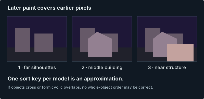
Suppose a long object passes through a building: its far end should be hidden by the building, while its near end should cover it. Sorting the whole object gives it only one place in the sequence. Either order draws part of the overlap incorrectly. Keeping scenery pieces small and controlling their internal face order helps the authored city work within this constraint.
Our first reconstruction exposed another detail of this sorting rule. While driving through a tunnel, the Wrecker—a large ground vehicle with a roller at the back—would briefly acquire stripes of floor markings across its roller. Sloping tunnel faces could cover it too. We were drawing those surfaces after the vehicle, letting them overwrite its pixels. The missing detail was a change in the sorting calculation: moving objects add their extent to the key on the surface and subtract it underground. Applying that underground adjustment put the surfaces back behind the Wrecker.
The same lack of a depth buffer also enables one of the game’s prettiest illusions. We will return to it at the fountain.
Sources: scene ordering, view-dependent model rules.
Clip before dividing, then fill the spans
Perspective division makes projected coordinates grow rapidly as depth approaches zero; behind the camera, the sign reverses. A polygon crossing that boundary would stretch across the screen or turn inside out. Darker handles this with two model paths.
For a model sufficiently far from the camera, the direct path projects emitted vertices immediately. For a nearby model, the near path retains signed 24-bit camera coordinates and clips against a plane at depth 32 before completing projection. A polygon cut by that plane gains intersection vertices; a fully hidden one disappears.
To find an edge’s crossing, the coordinate routine starts at the visible endpoint and repeatedly halves the edge’s coordinate differences. It moves towards or away from the clipping plane according to the current depth error, stopping when the error reaches zero or the depth step runs out of precision. These shifts and additions avoid a division for each coordinate. The shade of the new vertex is calculated separately, using the ratio of whole depths along the edge.
Projected polygons are then clipped to the rectangular viewport, in bottom, top, right, left order. Cutting off a corner replaces one vertex with two edge intersections, so a triangle or quad can emerge with more vertices. The filler accepts the resulting convex polygon.
Two edges and a horizontal run
The flat filler finds the top and bottom of the polygon and walks its two sides. On each scanline it obtains a left and right X coordinate, then fills the horizontal span between them. An edge’s slope tells the walker how much to add to X for each new row; fractional bits retain the part smaller than a pixel. The inner loop becomes a run of writes between two endpoints.
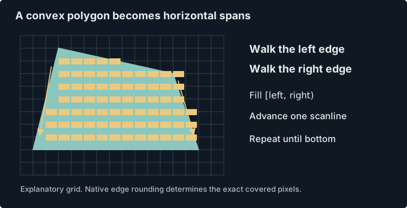
Darker starts edge fractions at 128, advances before the first scanline, rounds negative slopes differently on the two sides, and starts the right walker one unit beyond its vertex. Horizontal spans include their left end and exclude their right end; the top row is included and the bottom excluded. Those details determine whether adjoining faces meet cleanly.
Gouraud shading
Flat polygons have one colour. A Gouraud polygon supplies a shade for each vertex and interpolates the shade down its edges and across its spans. The artist stores those vertex shades in the model. Put brighter values along the middle of a pedestal and darker ones at its sides, and a few flat surfaces begin to suggest a rounded column.
The interpolation runs in palette-index space, producing bands of discrete colours from the selected ramp. Narrow spans may advance by more than one shade per pixel; wide spans repeat a shade across several pixels, distributing the remainder with integer error tracking.
Pressing F9 selects the flat fallback for shaded commands. The model’s flat-distance threshold can make the same choice at range, which explains the original’s visible switch to smoother shading as a building approaches.
Sources: flat filler, Gouraud filler, near clipping.
The palette is part of the lighting engine
A polygon’s colour byte splits into two fields:
ramp  = colour & 0xE0       // upper three bits: one of eight ramps
shade = colour & 0x1F       // lower five bits: position within that ramp
For ordinary shade codes 0–27, the renderer looks up a replacement shade, then combines it with the original ramp. Codes 28–31 take a special dynamic-colour path. Their palette entries have other uses, including sky colours.
Distance chooses a table
At setup, the game builds 60 rows of 28 shade replacements for surface scenes, or 28 rows underground. Each row maps the model’s authored shades to another set of indices. As the row number increases, they converge on shade one. The table is small: the surface version needs only 1,680 entries.
One row is selected for an entire model, using the forward depth of its origin. All its ordinary face and vertex shades go through that row. Depth-based dimming is thus reduced to one row selection and a lookup for each authored shade.
You can see the table at work while flying. Buildings change brightness in steps, and their gradients compress at range as several authored shades map to the same output. Turning the camera can also change a building’s shade: its forward depth changes as it moves towards the edge of the view, even while its distance from the aircraft stays roughly the same.
For an ordinary surface model, the relevant calculation can be expressed as:
adjusted_depth = uint16(origin_depth + 16 × (255 − beacon_strength))
row            = min(adjusted_depth >> 8, 59)
output_index   = ramp + shade_table[row][shade]
The conversion to uint16 wraps the adjusted depth into a word. The near-clipped path first clamps a negative origin depth to zero; underground uses its shorter table.
Try the actual shade-table arithmetic
At depth 4096 and full light, row 16 maps authored shade 24 to shade 18. Enable JavaScript to explore the calculation.
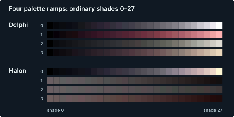
Each row represents 256 camera-depth units. The swatches use the source palette and the game’s integer shade-table formula. Halon always supplies light strength 255; Delphi uses the selected beacon strength.
Why Halon’s haze feels different
In Delphi, ordinary ramps mostly converge towards dark colours. Distant buildings become silhouettes against the purple horizon. Halon’s palettes include ramps whose low entries are grey or coloured haze, so the same shade lookup makes buildings blend into their surroundings. The arithmetic is shared; the palette changes the atmosphere.
Try switching palettes in the demonstration above. The authored shade and depth can stay exactly the same while the apparent lighting changes substantially.
Sources: exact shade-table construction and selection, palette resources and colour commands, palette atlas.
Beacons and the horizon
Delphi’s lighting strength comes from the state of a beacon on its nine-cell lattice. Each horizontal coordinate selects:
beacon_coordinate = 9 × floor((cell_coordinate + 4) / 9)
Applying this independently to the column and row assigns each object to a beacon’s 9 × 9-cell lighting region. The chosen beacon supplies the strength for that object. As a script fades a beacon, all the scenery assigned to it follows that change.
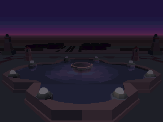
The strength affects both the distance-table selection and special dynamic colours. Streetlights dim along with nearby buildings because their drawing commands use these colours. At zero beacon strength, the original palette path still leaves a dim lamp visible above its pedestal.
The Caero also draws energy from this beacon lattice. Its charging calculation includes distance and height, so the aircraft gains more power near the light while the scenery uses a uniform regional strength. We follow that calculation in the flight-model article.
An infinite ground beneath a small city neighbourhood
Before the objects, the renderer draws a background of 17 palette-coloured bands. Their boundaries are placed from a short table of sixteen offsets, clustered tightly around the horizon. Pitch moves the horizon and roll tilts it. Integer sine, cosine and slope calculations turn those boundaries into spans.
At steep enough pitch the original can use one solid outer colour. That shortcut is appropriate to its narrow view; simply increasing field of view later can expose the assumption and leave sky or ground missing.
The lowest band supplies the ground colour all the way to the horizon. Roads, floor markings, cliffs and other terrain details are geometry drawn over it. As the local geometry fades into silhouettes, the background continues beyond it, suggesting a city larger than the part currently being drawn.
Sources: background bands, beacon lookup and scene lighting.
The fountain trick
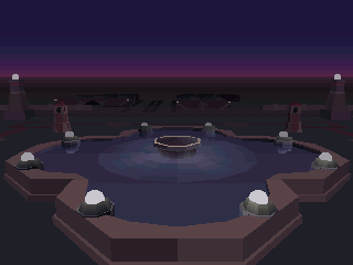
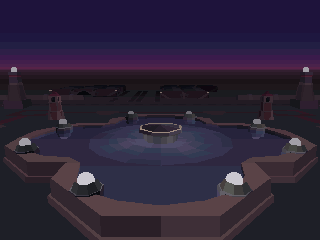
Kismet Square’s fountain is assembled from twelve placed components: two each of types 101–104 around the pool and one each of types 120–123 in its centre. The apparently rounded lights are screen-space discs. The pedestals, pool rim and moving central surfaces are polygons.
The reflections are one of our favourite discoveries in these models. Below each light is a second, tinted copy of its geometry, mirrored around the water level.
The upper disc of type 101 sits at height 608 in the exported model coordinates. Its counterpart sits at 160. The water is at 384: each disc is exactly 224 units from the water plane. Pedestal faces have similarly mirrored counterparts, with different colours. The reflected geometry is stored in the model.
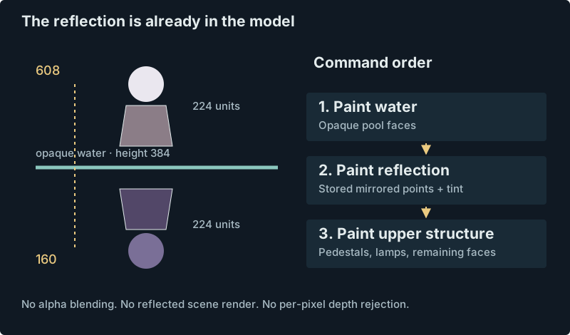
The water’s opaque polygons are issued first. Tinted reflected geometry is issued afterwards, followed by the remaining structure. With no depth buffer rejecting the below-water pixels, the reflection appears on top of the already drawn water. The upper and lower discs even use the same radius numerator; their different palette colours provide the tint.
A depth buffer would reject the reflection pixels because the water is closer to the camera. Darker’s painter ordering lets the model author override that geometric relationship simply by putting the reflection commands later in the program. The trick depends on the renderer’s usual weakness: later drawing always wins.
Moving the water
The central pieces read six height parameters. A routine updates those parameters from the game clock, the sine table and six amplitudes. Successive bands rise and fall at different phases, producing a travelling ripple. When the model interpreter reaches a parameter command, it replaces a coordinate component with the current height and continues drawing. The same stored program produces a new water surface each frame.
Its cycle is 2,048 source timer ticks, approximately 4.095 seconds at the measured timer rate. Reusing the original clock and arithmetic preserves the relationship between all four central pieces.
Explore the assembled animated fountain in the model inspector.
Other light effects are geometry too
Streetlights, landing approaches and the satellite building’s doorway use coloured polygons on the ground to suggest pools of light. Those patches are painted opaquely like the rest of the model, which has an odd consequence: a dark edge of a light patch can cover ground that was already brighter. This is especially noticeable when distance shading changes the balance between the patch and its surroundings.
The disc instruction takes the most recently emitted point as its centre and divides a stored radius numerator by projected depth. The rasteriser writes a small circle in screen space. A tower’s glowing head therefore needs just one point and a radius, and remains round from every angle. At tiny radii, the integer circle’s uneven coverage gives distant lights their characteristic twinkle.
Sources: exact fountain construction and command order, animation parameters, disc rasteriser.
Smoke, fire and moving objects
Combat effects combine recipes of timed emitters with small bitmap sprites. A recipe gives emitters different delays, lifetimes, radial motion and height changes; sound layers accompany some recipes.
The original has separate pools for 25 moving recipe emitters and 20 trail sprites. Each emitter can produce several visible samples—for example, a ring of fire spreading away from an explosion. When a pool fills, the oldest active record can be reused.
Effect drawing joins the world’s ordered records. A ring-shaped recipe is projected as a sequence of samples, with its own arc traversal. Depth selects stored sprite artwork at sizes 16, 12, 8, 6 or 4 pixels, eventually reducing the effect to a single point. A mask specifies which pixels to copy at each size.
Sorting the effect records with the scenery lets buildings cover explosions and smoke. It also gives effects the same overlap problems as other large objects: a spreading ring can straddle scenery that has only one position relative to it in the draw order.
Moving aircraft use the shared model interpreter with their own orientation. Their distant-point representation reduces the whole model to one pixel. That path reuses shading state left by the preceding mesh, so the colour of a distant aircraft can depend on what was drawn just before it.
Sources: effect recipes and native comparisons, particle projection and drawing.
Putting the cockpit around the world
The cockpit is assembled from bitmap artwork, then updated with instruments and overlays. The world is clipped to the appropriate viewing rectangle, and the cockpit’s irregular edges are composed around it.
The 320 × 200 source sheet is an atlas containing instrument states and other pieces that will be copied elsewhere. To assemble the cockpit, the game copies rows 0–135 into a 320 × 240 cache, then copies rows 96–199 into destination rows 136–239. Reusing an overlapping source range lets the cockpit occupy a taller display than the sheet it came from.
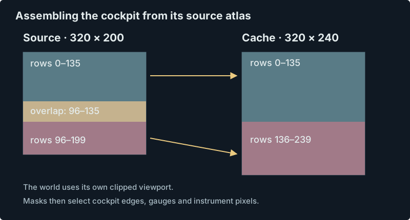
Instrument changes copy narrow masked strips from this cache or from their lit states. Decreasing a gauge restores the appropriate background strips. Where masks overlap, the last update wins, leaving a few pixels dependent on the order in which the instruments changed.
The masks specify which pixels to copy and which to leave untouched. A copied pixel can use any palette index, including black. HUD lines, crosshairs and target outlines add procedural drawing; text uses packed glyph masks and palette colours.
Writing to VGA
The retail startup enters BIOS mode 13h and then reprograms VGA timing for 320 × 240. The drawing code works with VGA plane masks and specialised span/blit routines. Pixel alignment matters enough that some sprite and glyph data has separate forms for different horizontal alignments.
Conceptually, the finished picture is still an indexed image. The palette’s RGB values go through the game’s brightness/fade handling and VGA DAC conversion. Changing a palette can recolour pixels without repainting their indices.
Darker C++ keeps a linear indexed buffer and expands it to RGBA for the host display. That gave us a convenient comparison point during reconstruction: we could compare the indices written by a recovered routine with those written by the original x86 instructions, before palette conversion.
Sources: cockpit transfers and masks, VGA startup observation, palette decoding and fades.
Where the work is saved
Several of these techniques save work by moving decisions earlier. Model authors supply gradients and internal drawing order. Setup builds the distance-shade tables. Cell selection discards most of the city before any vertices are transformed. The drawing interpreter reuses products it has already calculated.
The resulting trade-offs are visible throughout the game:
| Cost | Darker’s response | Visible trade-off |
|---|---|---|
| Large vertex streams and repeated transforms | Reuse coordinates, negate cached contributions, call shared routines | Stateful interpretation and rounding quirks matter. |
| Considering the whole city | Local grid traversal and extent rejection | Limited view distance; edge cases at admission boundaries. |
| Solving visibility at every pixel | Background list, ordered model records and authored face order | Some overlaps cannot be resolved correctly. |
| Many finely shaded distant faces | Per-model flat fallback and eventual object points | Detail can change abruptly with distance. |
| General dynamic lighting and fog | Authored shades plus small palette lookup tables | Quantised brightness and model-wide changes. |
| Arbitrarily scaled particle artwork | A few sprite sizes, masks and distant points | Size transitions are discrete. |
For how beacon power affects the aircraft itself, see Inside Darker’s flight model, including Caero lift and braking, the Skimma’s different rules and underground guidance.