Earthsiege puts a surprising amount of machinery into a small picture. Beyond the cockpit are articulated walking tanks, detachable weapons, textured buildings, explosions, a rolling horizon and drifting clouds. The display contains just 64,000 pixels. Every one is written by software running on the CPU.
Released by Dynamix in 1994, Metaltech: Earthsiege is a combat simulator in which you pilot a HERC, a heavily armed walking vehicle. Surviving a battle is only part of the job. You also need to recover enough equipment to keep your squad fighting. Here we will follow the other half of that simulation: how the renderer turns a world full of machines into the view through your windscreen.
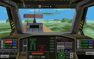
The executable contains a C++ object system and Dynamix's 3Space model machinery, alongside specialised integer and assembly drawing routines. We recovered their behaviour from the executable and game files. The explanations and pseudocode below are our own; we do not have the original source tree.
Most illustrations come from running the original instructions with controlled inputs. We provide the file reads, memory and emulated VGA hardware, then let the game transform vertices and write pixels. Diagrams and synthetic test shapes are labelled separately. The supporting rendering notes contain addresses, test coverage and the remaining differences between this software renderer and our browser exhibits.
A frame in six stages
A useful starting point is to separate the things that change a vertex from the things that change a pixel.
An animated model begins in its own coordinate system. Part transforms assemble it, the object transform places it in the world, and the camera transform expresses that world relative to the eye. Lighting assigns brightness. Clipping trims polygons that cross the viewing boundaries. Perspective converts their surviving vertices to screen coordinates. Finally, a rasteriser fills the space between those coordinates.
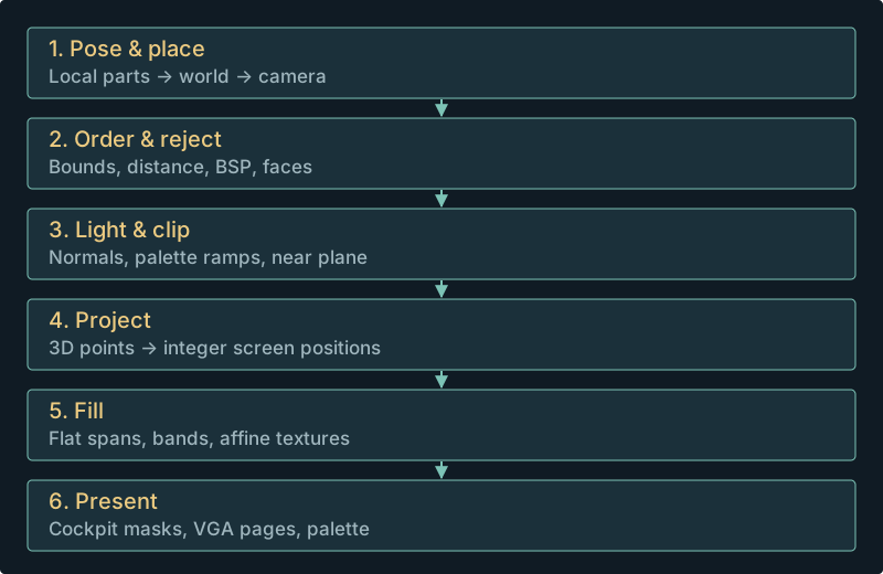
Drawing order matters throughout. The background goes down before ordinary scenery and actors. Within the cockpit, masks keep the world inside the windows. Instruments occupy their own regions, some of which are retained between frames. The final display is assembled in VGA memory and made visible by selecting the appropriate page.
There is no depth buffer in this path. A polygon can overwrite an earlier polygon without asking which is closer at each pixel. Getting the order right is therefore part of rendering an object, rather than a problem left to the pixel writer.
A HERC is a tree of parts
A Samson is stored under the rather less distinctive name HERCULES.DTS. Its model contains multiple shapes, articulated parts, meshes, animation channels and material references. That organisation gives the renderer something much more useful than a single bag of triangles.
A leg can move relative to its parent, while the entire machine moves across the battlefield. The pose supplies local rotations and translations. Following the hierarchy composes these into the transform needed to draw each mesh. A child inherits its parent's movement, so changing a joint does not require rewriting all the model's vertices.
Weapons complicate the tree in an interesting way. The chassis contains attachment placeholders. At runtime, the game substitutes weapon wrappers at those positions. Each wrapper owns its cell selection, shares the appropriate skeleton state and switches to the weapon texture bank when drawing. Some invisible helper polygons still contribute transformed vertices. Omitting everything that does not draw would break the assembly.
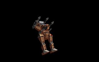
Original drawing
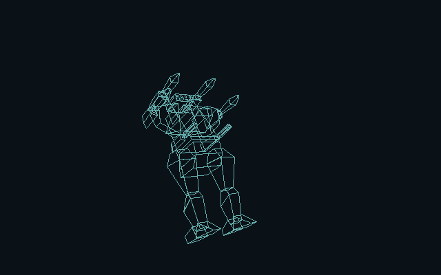
Submitted primitive boundaries
The tree also provides cheaper ways to draw a distant machine. HERC detail selection uses projected-size thresholds of 75, 60, 45, 25, 18, 12 and 6, with quality and distance adjustments. The top-level selection is separate from detail parts nested inside a shape. This is why “show every polygon” involves more than disabling one distance check.
A scene may also contain flat-colour faces, lit faces, Gouraud-shaded polygons, textured polygons, lines, points and scaled bitmap effects. These eventually reach a small set of pixel-writing routines, but their preparation differs. A bitmap explosion does not need the same mesh traversal as a HERC's torso.
Coordinates without floating point
Earthsiege uses X across, Y forward and Z up. Camera depth is therefore Y. This differs from the common modern convention of looking down a Z axis, and is an easy source of sideways or upside-down models when writing a new viewer.
The transform routines use fixed-point arithmetic. A complete turn is 65,536 angle units; a quarter turn is 16,384. Rotation matrices use a Q14 representation, where the integer 16,384 represents 1.0. Multiplying a coordinate by a matrix component produces a result that must be shifted back down to the coordinate scale.
For example, a matrix component of 8,192 represents one half. Multiplying a coordinate of 100 by that component gives 819,200; shifting right by 14 returns 50. This representation makes rotations possible with integer multiplications and shifts. Lookup tables supply the trigonometric values.
The important complication is rounding. A sequence of fixed-point rotations and translations loses fractional information at particular points. Combining those operations into one floating-point matrix and rounding only at the end can move an edge by a pixel. Our reconstruction preserves the original order of shifts, divisions and additions.
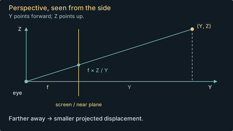
Once a point is in camera coordinates, the basic perspective calculation is familiar:
screen_x = centre_x + focal_scale * X / Y
screen_y = centre_y - focal_scale * Z / Y
The minus sign makes an upward Z displacement move towards the top of the screen. Greater depth makes the same displacement appear smaller. In the ordinary perspective setup, the focal scale is 256, represented as a power-of-two shift. A separate parallel-projection path uses a divisor instead.
Clip before dividing
A polygon can have one vertex behind the camera and the rest in front. Dividing all its coordinates by depth would produce enormous or inverted screen positions. The renderer first clips it against a near plane.
At each crossing, it creates a new vertex on that plane. Texture coordinates and vertex-light values must be interpolated along with position, or the clipped edge would acquire the wrong texture or brightness. For an edge from A to B, the crossing fraction is (near - A.y) / (B.y - A.y). Each new attribute is A's value plus that fraction of the change from A to B; the original routines perform this with their integer rounding rules.
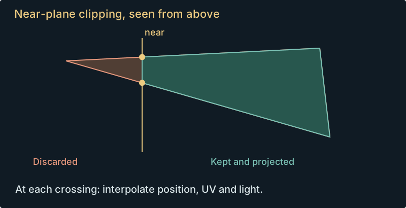
There is a revealing shortcut here. The ordinary near distance equals the focal scale. At an intersection, focal_scale / depth is therefore one. The original clipper adds intersection X and minus Z directly to the screen centre. A general-purpose replacement that allowed those two distances to vary independently would miss this assumption.
Even equality has two treatments: model polygons classify depth exactly on the near plane as clipped, while the terrain path retains it. These small distinctions show up in controlled tests long before they are easy to spot during a battle.
Drawing the far side first
With a painter's algorithm, later paint covers earlier paint. Earthsiege uses two kinds of ordering to make this practical.
At the world level, it builds an object ordering tree. Comparing centre distances is sufficient for simple cases, but a large building can extend past another object even when its centre is farther away. Some scenery records therefore contain a pair of line-segment endpoints. The engine transforms those endpoints into world space and uses observer-relative separating planes to resolve overlap. Extended scenery enters the tree before ordinary point objects; traversal visits left branch, object, then right branch.
Inside a model, authored binary space partitions provide a finer ordering. A BSP node describes a partition of space. The eye's side of that partition determines which child is farther away and should be visited first. Moving the camera across it changes the traversal order.
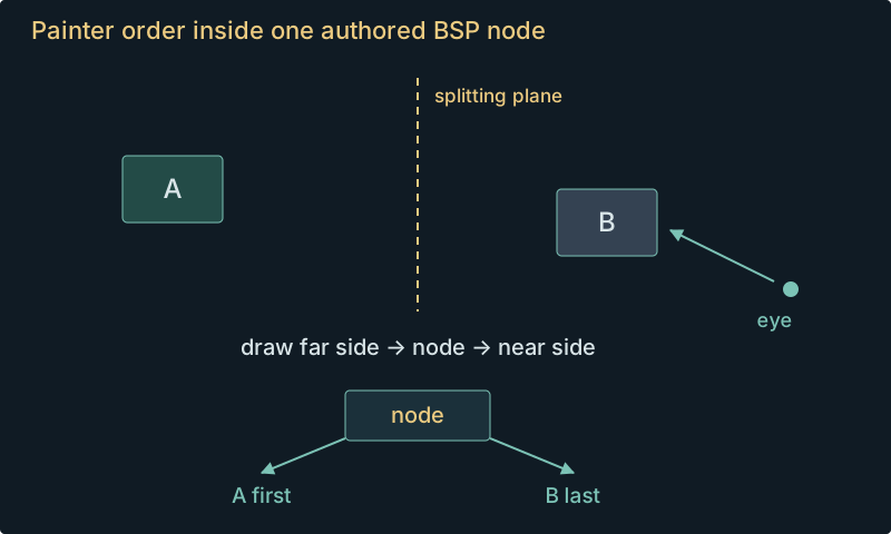
Face orientation removes surfaces that should not be seen from the back. Two-sided materials take a separate back-face path, including a fresh lighting calculation with the reversed normal. None of this guarantees that arbitrary intersecting geometry can be drawn correctly. It works with the ordering information and model conventions supplied by the artists and tools.
The slider counts raster submissions, not authored faces. One shaded face can become many flat strips, and clipped geometry can acquire extra vertices. That distinction becomes visible in the next stage.
Lighting is a choice of palette colour
Each screen pixel stores an eight-bit index into a palette of 256 colours. The renderer does not have to calculate and store red, green and blue for every pixel. It has to choose the right index.
Materials refer to shade ramps, ordered lists of palette colours. A dark brown, a slightly lighter brown and so on form the available brightness levels for one material. An intensity selects an entry in that ramp. The palette supplied for the mission determines what those entries actually look like.
Lighting begins with normals, vectors describing which way a surface faces. A dot product measures how closely a normal points towards a light. Earthsiege transforms lights into the model's coordinate system, so the normals can be used with the local geometry.
The persistent directional light has intensity 256 and direction (-1099, -984, -1421). Model lighting uses a wrapped response: a face perpendicular to this light still receives half of its directional contribution. That helps keep the sides of a HERC readable. The terrain lighting path uses a different, one-sided response. Assuming one universal lighting formula made our early inspection renders misleading.
Dynamic lights add another economy. The renderer admits ten lights, including the persistent one. A separate manager holds up to twenty effect sources and chooses their representation for each object. A sufficiently distant source can be approximated as directional; nearby objects retain its position. The available renderer slots are filled in source iteration order, without a nearest-light sort.
Smooth shading made from flat strips
Gouraud shading assigns brightness to vertices and varies it across a face. Earthsiege first converts those vertex intensities into palette-ramp indices. It then divides the polygon into a triangle fan and constructs a solid-colour strip for each successive palette index within a triangle.
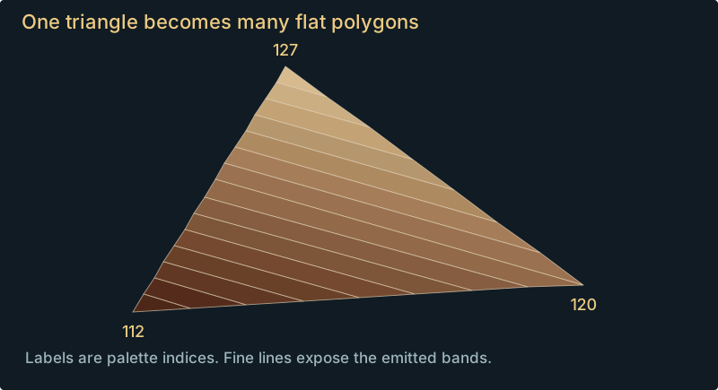
See the original raster for this triangle
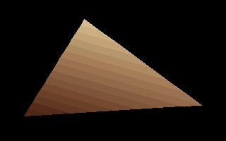
Each strip goes through the ordinary flat-polygon filler. This reuses an existing fast drawing path and matches the limited colours available in the palette. The tradeoff is quantisation in both colour and geometry: every band computes its own rounded edge positions. Interpolating RGB in a modern shader produces a smoother result, but different pixels.
The edges decide which pixels exist
A polygon filler needs the left and right extent of each covered row. The original flat filler walks its edges with integer Bresenham-style stepping, then writes inclusive spans between the resulting endpoints. The final row is included too.
There are asymmetric rules for shallow left and right edges and for tied top or bottom vertices. Viewport clipping also matters: the original clips a complete horizontal slab, then a vertical slab, calculating crossings from the outside endpoint. Replacing this with four independent half-plane passes can round a corner differently.
These details explain why an apparently reasonable renderer can leave hairline gaps or change a silhouette. Matching the projected vertices alone does not establish that the same pixels will be filled.
Textures across a whole polygon
A texture coordinate, usually called U or V, identifies a location in a bitmap. Once a textured polygon reaches the screen, its mapper has to produce a texture coordinate for every covered pixel.
Earthsiege uses affine interpolation with Q16 steps. It walks paired polygon edges and interpolates between them across a span. Ordinary rectangular views use columns; cockpit clipping-region mode uses rows. Samples start at a half-step offset, use the original integer rounding and include the span endpoints.
This is not perspective-correct interpolation. A perspective-correct mapper would carry quantities such as U/depth, V/depth and 1/depth, then divide to recover U and V at the pixel. Earthsiege's affine path avoids that work, at the cost of distortion on receding surfaces.
There is another trap for a modern renderer. Dividing a quad into two triangles changes how affine texture coordinates vary across it. The whole-polygon mapper can produce a different pattern from either diagonal split. That was the cause of the bent stripes we first saw on the gun tower and listening post in our browser viewer.
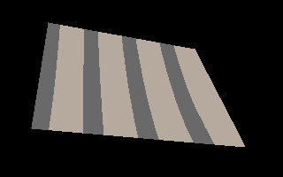
The alternate view above demonstrates the interpolation difference. It is not intended to reproduce the original edge coverage. Our model gallery now accounts for the whole-polygon mapping, while the authentic native renderer also preserves the integer sampling and clipping rules.
Texture lighting uses eight palette translation tables. A texel's source index selects an entry in the chosen table, which yields the destination index. There is a subtle transparency distinction: without a translation, source index zero is transparent; with one, every texel is written, including translated zero.
Distance haze leaves textures behind
For many untextured materials, increasing distance selects new shade ramps that converge towards the environment's distant colour. Model textures continue to use their light-level translation tables. Those tables do not receive the object's distance haze.
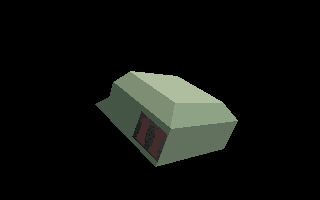
Near shade band
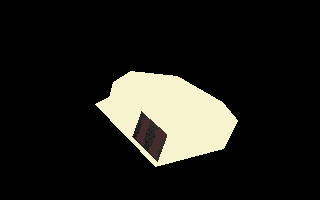
Far shade band
Day, dusk and night palettes still affect those textures. The exception is specifically their response to object distance. The separate ground-texture renderer has its own distance translation, so it should not inherit this rule.
A world underneath the objects
The distant landscape begins with a cheaper representation than a terrain mesh. Sky and ground palette bands establish the horizon. At higher detail, a perspective-mapped ground image replaces the ground bands. A bitmap panorama supplies distant hills. Clouds are then drawn over the background; scenery and actors follow in their own pass.
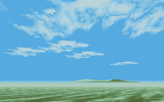
The ground image is TRENCHES.64K, a 256 × 256 field of palette indices from F0 to FF. Height and horizon position determine its perspective sampling; heading rotates the sampling axes. World X and Y wrap to sixteen bits. Translating the camera by 65,536 units along both axes reproduces the same cloud-free background.
The panorama is a scrolling bitmap strip. Heading chooses the horizontal section, and camera roll rotates its drawing. Those mountains are not finite-distance objects you can reach. Low-visibility world descriptions can omit the panorama entirely.
Clouds have their own small field of up to twenty objects. Their wind is selected during initialisation. Each cloud draw advances active positions by that wind vector, without multiplying by the simulation's frame-time ratio. This dependence on drawing became important when comparing recorded flights: the original stops drawing the world while the lower cockpit panel is stable. Updating hidden clouds anyway brings them back in the wrong place when the player looks up.
The supplied mission environments combine four terrain families, three times of day and two visibility settings. These select palettes and world descriptions at launch. They do not implement a continuously travelling sun. The sky exhibit lets you compare all 24 combinations and unroll the horizon artwork.
Drawing through the cockpit
The cockpit is both a frame around the scene and a set of rules for where drawing may occur. Its ED resources describe clipping regions, including curved window boundaries.
For solid polygons, rectangular regions clip vertices before edge construction. Curved regions intersect the completed row spans instead. The texture path switches to row traversal and clips its spans. Treating every window as a final per-pixel mask misses the rounding changes introduced earlier in those paths.
The view origin also matters. Earthsiege derives the projection centre from the viewport, the VUE projection origin and the canvas origin. Side windows continue the same perspective plane; they are not each rendered with an independently turned camera. This keeps the cockpit's openings consistent with one view of the world.
The lower instruments require a different drawing policy. Static artwork, radar, status displays, damage indicators and live values are updated and copied in regions. Clearing and redrawing a whole screen every frame would discard the page contents that those updates expect to retain.
This even affects the palette. In one comparison, our reconstruction uploaded a shield palette during a transition where the original reused the existing page. The VGA upload routine also zeroed the red component of the next palette entry, so the extra upload changed an unrelated colour. Removing the unnecessary operation fixed the image. The visible defect was a colour mismatch; its cause was ownership of a cockpit redraw.
Four planes behind the screen
The output routines target VGA's planar memory arrangement. In the unchained 256-colour modes used here, four neighbouring screen pixels belong to four different memory planes.
For a screen position X, the plane is X & 3. The byte position within that plane includes X >> 2, plus a stride for each row. At 320 pixels across, each plane contributes 80 bytes per row.
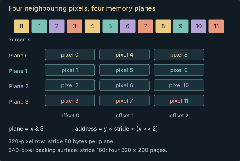
A flat span writer can exploit this organisation: enable several planes and one CPU write can affect several neighbouring pixels. Textured pixels need different values and use more specialised writers. Port and mask setup has a cost, so the drawing code tries to do useful runs of work under each configuration.
The live game's 640 × 400 backing arrangement holds four logical 320 × 200 pages. Its per-plane row stride is 160 bytes. Those pages support presentation and cockpit preparation; the display controller's start address chooses which area becomes visible. Four complete indexed images occupy 256,000 bytes, fitting within VGA's 256 KiB.
This is why reproducing just a visible 64,000-byte array was insufficient for our reference harness. The original instructions also expect hidden page contents, VGA plane masks, address calculations and display-start changes to behave correctly.
What changed in the expansion?
The March 1995 expansion changes the simulator substantially, particularly its weapons, arrivals and resource loading. The underlying graphics mathematics is much closer to the base game. All 3,200 retained base projection and near-clipping cases produce the same results in the expansion's default mode; 512 rotation-matrix cases are byte-identical too.
There is also an extra lowercase -v command-line path. It selects a 320 × 400 VGA mode and doubles the vertical perspective scale. The -v1 layout shows the upper and lower cockpit together. Bare -v and -v2 expose overlap or misplaced instruments in our captures, so the suffix matters.
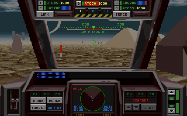
Default expansion display
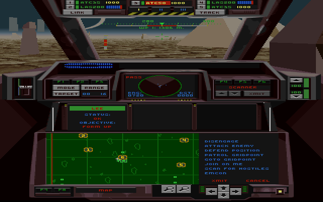
Expansion with -v1
We have established what this path does, but have not found a supplied explanation of its intended use. It deserves further historical investigation. Its presence does not make the renderer resolution-independent: view layouts, buffer dimensions and projection assumptions still need to agree.
The later expansion revisions make much narrower changes. The floppy executable repairs a scanner transform dependency. The April patch also collects retired effects after damage and releases a radio-message start latch. The simulator comparison gives the instruction evidence, controlled probes and build provenance, including the expansion's new weapon behaviour.
Following the pixels back to the code
A useful rendering investigation needs checks at several scales. A tiny synthetic polygon makes edge rounding easy to see. A complete armed HERC exposes hierarchy and texture-bank mistakes. A recorded cockpit frame adds camera timing, page reuse and palette state.
For the base renderer, we compared all 401 supplied model roots from eight directions, then added animated poses, equipment assemblies and complete scenes. After controlling presentation timing, 114 of 120 sampled gameplay images matched exactly. The remaining six differed only at a malformed radar model that reads unavailable vertices. We documented and repaired that input in the reconstruction; applying the same repair to the original renderer makes those images agree too. The full test conditions and captures are recorded in the comparison notes.
Earthsiege's appearance comes from the whole chain: fixed-point poses, authored draw order, palette ramps, strips of smooth shading, whole-polygon texture interpolation and the state of four VGA pages. The most useful discoveries often began with something small in the picture. A crooked stripe exposed a different interpolation scheme. A cloud in the wrong place exposed a drawing-dependent update. A shield colour exposed an extra palette upload. Following those differences through the instructions has given us a much clearer account of how this renderer works.
Further reading and reproducibility
The detailed notes cover rendering, lighting, environment drawing, animation, file formats, build evidence and full-frame comparisons. Addresses refer to the October 1994 base simulator unless a note names another build.
Illustration provenance records the original executable hash and capture sources. The article asset manifest records the published files, including explanatory diagrams. The site repository includes the import and checking scripts; the analysis generator is tools/build_graphics_article.py in the research workspace.
Fabien Sanglard's Build engine analysis was an inspiration for this illustrated walkthrough. Earthsiege tackles a different kind of scene, and taking its renderer apart one stage at a time has been just as rewarding.