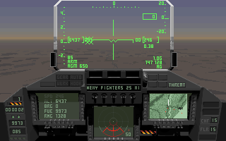
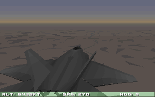
Pull back on the stick in TFX and several things happen before the nose moves. The controls are filtered, trimmed and limited. Flaps may move automatically. The F-22 may redirect its exhaust. The resulting forces change the aircraft’s velocity, while moments turn its body. Meanwhile, fuel is disappearing from a mass calculation that also affects how quickly the aircraft can roll.
There is a lot of machinery behind that small green G meter.
TFX arrived in 1993 with three very different aircraft: the Eurofighter 2000, the F-117A Nighthawk and the F-22, called the Superstar in the manual. Two were still future service aircraft. Roderick Victor Kennedy, the aeronautical engineer credited with the flight model, described using prototype information, calculations from aircraft geometry and estimates to fill the gaps. The manual even devotes an appendix to forces, moments, lift and drag.
We can now follow those ideas into the executable. This article looks at the September 1994 DOS release, TFX 2.05, using the original routines and our C++ reconstruction. We will start at the realism menu, work through an airborne update, then follow the aircraft back onto its wheels. Along the way there are some unexpected discoveries: a carrier-specific F-22, weather tables that the game scarcely uses, and a drag readout that never reaches the flight equations.
Four choices, two families
The four flight models are more than different sensitivity settings. They divide into two families with substantially different ways of moving an aircraft.
| Model | How it flies | What the controls command |
|---|---|---|
| Arcade | Moves along the aircraft’s forward direction. Speed approaches a requested Mach number within an altitude-dependent envelope. | Filtered mouse movement turns the attitude directly. |
| Simple | Uses the same basic speed system, with bank-induced turns, speed-dependent manoeuvre limits and more elaborate stall and ground handling. | Keyboard or joystick requests pitch and roll rates. |
| Realistic | Calculates lift, drag, thrust, gravity, wind-relative airspeed and mass. Rotation and landing are simplified. | Computes an equilibrium angle of attack and roll rate, then applies them to the attitude. |
| Military-spec | Uses the aerodynamic force model, integrates pitch and roll moments, and evaluates individual wheel and body contacts. | Control-surface and nozzle commands produce forces and moments. |
The distinction between Realistic and Military-spec is especially useful. In Realistic, the game works out an angle of attack that balances the current pitch equation and moves the aircraft towards that orientation directly. In Military-spec, the pitching moment accelerates a pitch rate, which then changes the attitude. Rotational inertia and damping have time to act. The result has more of the aircraft’s own motion between the player’s command and the new view through the windscreen.
The campaign selection is separate. An Arcade mission and the Arcade flight model are different settings. So are the individual switches for wind, temperature, precipitation, crashing, gear damage and G effects. Choosing a more detailed flight model does not automatically select every other realism option.
There is another wrinkle: the selected model is not always the routine running this frame. Switching on autopilot in Arcade or Simple hands flight to an advanced callback. Automatic landing and a disabled aircraft each have their own paths too. We will return to those after the ordinary flight model.
Code: player callback selection, Realistic attitude commands.
Three aircraft, three sets of numbers
The aircraft presets live in executable code. Each setup routine writes its wing geometry, mass, control derivatives, engine ratings, wheel positions and other parameters into a shared collection of variables. The pictures in the model files are independent of these physics dimensions.
Here are some of the values used by the advanced models. Thrust is for the complete aircraft with both engines healthy, at sea level. The fuel figures are kilograms, although the cockpit also uses its own scaled fuel readout.
| Game parameter | Eurofighter | F-117A | F-22 |
|---|---|---|---|
| Empty mass | 10,000 kg | 13,608 kg | 15,000 kg |
| Internal fuel | 4,000 kg | 7,938 kg | 9,979 kg |
| Wing area | 50 m² | 105.9 m² | 78 m² |
| Wing span | 10.5 m | 13.2 m | 13.56 m |
| Mean chord | 5.697 m | 6.4 m | 5.697 m |
| Full dry thrust | 120 kN | 96 kN | 187.2 kN |
| Additional full reheat thrust | 60 kN | None | 124.8 kN |
| Afterburner steps | 4 | 0 | 4 |
| Control-law G limits | +9 / −3 | +6 / −1 | +9 / −3 |
| Stored low-speed stall reference | 64.375 m/s | 92.7 m/s | 67.98 m/s |
| Cruise Mach setting | 0.70 | 0.85 | 1.20 |
The stall reference is used by ground and control logic. It is not a universal airborne speed below which the entire simulation declares a stall: the aerodynamic wing calculation also checks angle of attack, available lift and flap operation.
The Nighthawk’s shape produces a particularly different set of rules. It has no afterburner, no automatic high-lift flap system and no thrust vectoring. It also has lower positive and negative G limits. Its lift slope is constant with Mach, unlike those of the two fighters. Its generous wing area does not make it a substitute for a fighter with working flaps and a much stronger engine.
The Eurofighter uses the sign and travel of a foreplane in its pitch-control parameters: its maximum elevator angle is about −50°, against +6° in the other two presets. Those angles are multiplied by different aerodynamic derivatives. A raw angle alone therefore tells us very little about the resulting nose-up authority.
The F-22 adds differential exhaust-vector control. Its carrier setup also changes the numbers: wing area rises from 78 to 86 m², the landing sink-speed reference rises from 3.05 to 4.572 m/s, and an otherwise zero air-brake drag coefficient becomes about 0.02769. This is a separate physical configuration selected for a carrier start.
Code: aircraft preset decoding and carrier setup. The three decoded profiles also match execution of the original setup routines.
What happens in one update
A force has both a magnitude and a direction. Lift, drag, thrust and weight cannot simply be added as four positive numbers: they point in different directions, and the directions change when the aircraft banks or pitches.
TFX uses two coordinate systems for the advanced physics. The world frame is north, east, down, with positions in metres. The aircraft’s own frame is forward, right, down. An orientation matrix describes where those three aircraft axes point in the world.
Ground velocity is stored as a world vector. Subtracting the wind gives the velocity through the air. Project that vector onto the aircraft axes and we have forward speed, sideways speed and downward speed as experienced by the aircraft.
Angle of attack, usually written α, measures the difference between the aircraft’s forward axis and the direction of its motion through the air in the vertical plane. It is not the pitch of the nose relative to the horizon. An aircraft can be descending with its nose above the horizon and still have a large positive angle of attack.

The main update proceeds in this order:
- Measure the airUpdate wind, transform velocities, add empty mass, fuel and stores, then calculate density, Mach and dynamic pressure.
- Choose the coefficientsMach changes the lift slope, wave drag, stability and control derivatives.
- Process engines and controlsBurn fuel, advance faults, read the pilot or autopilot, trim and limit the controls, and set flaps and nozzles.
- Build the loadsCalculate aerodynamic, engine and ground forces and moments.
- Move the aircraftCombine the loads with gravity, divide by mass and inertia, update velocity and rotation, then advance position.
- Publish the viewNormalise the orientation, apply the cockpit’s position within the airframe, and export the renderer’s coordinates and instruments.
The ordering leaves a little history in the calculation. Fuel consumption, for example, sees the previously calculated thrust. Some control limits use the preceding surface forces. The equations form a running system whose state carries from one update to the next.
Code: complete advanced update, air data.
Air gets thinner, but not quite as advertised
Dynamic pressure is the common multiplier behind much of the model:
Here ρ is air density, V is speed through the air, S is wing area, and CL and CD are lift and drag coefficients. At a fixed coefficient, doubling airspeed gives four times the force. That is why an elevator that seems ineffective during the takeoff roll becomes powerful once the aircraft is moving quickly.
Density is an inexpensive altitude approximation. For altitude h in kilometres, the first calculation is:
Above 10 km, TFX adds 0.00088 × (h − 10)², then applies a lower limit of 0.088 kg/m³. At sea level density is 1.225; at 10 km it is about 0.408. This is an authored curve, rather than a full atmospheric pressure calculation.
Temperature follows a 6.5 K-per-kilometre lapse up to 11 km, then remains constant. The speed of sound is sqrt(401.8 × temperature_in_kelvin), and Mach is airspeed divided by that result. Temperature therefore changes the Mach-dependent coefficients. It does not enter the density formula. Raising the temperature does not directly thin the simulated air at the same altitude.
The weather tables suggest something more elaborate than the code actually delivers. There are five wind profiles and twenty temperature values. The retail physical initializer selects wind profile zero, and the temperature-column variable remains zero. Switching temperature on therefore selects 29°C, converted with the original +273 to 302 K, across the reference game’s environments. Switching it off selects 288.15 K. The manual describes regional and time-of-day variation; that selection never materialises in this startup path.
Wind still changes the flight. A random surface-wind target is approached by moving 5% of the remaining difference each update. Sines modulate its direction. After an initial 120-second interval, new target speeds arrive at intervals between 60 and 240 simulated seconds. Environment flags boost wind strength, so choosing a storm can still have an effect even though the base profile does not change.
Above 6 km, another horizontal wind component begins to enter, reaching full strength at 10 km. It is added to the lower wind rather than replacing it. Profile zero supplies a value of 100 directly to the metre-per-second velocity calculation, aimed east. The vertical-gust calculation exists too, but its amplitude variable is initialized to zero and has no writer. In ordinary flight, that branch contributes no vertical wind.
The surviving tables, unused gust fields and fixed profile selection make the weather system feel partly finished. The active horizontal wind, however, reaches the airspeed calculation before every lift and drag evaluation. A headwind can let the wings support the aircraft at a lower speed over the runway; the wheels still experience the actual ground motion.
Code: atmosphere, wind, original environment-to-weather comparison.
Lift, flaps and the shape of a stall
The wing starts with a straight-line lift rule: a lift slope multiplied by angle of attack, plus a small zero-angle offset. Flaps change both the offset and the allowable maximum.
TFX automates two distinct flap effects on the fighters. The first estimates how much flap is needed to support the current weight at the current dynamic pressure. As fuel burns, speed rises or density increases, the required fraction falls. That fraction adds lift at all angles and raises the positive lift limit.
The second responds when the requested wing lift exceeds that limit. It progressively spends the extra lift available from the automatic leading-edge system. Once the extra allowance is exhausted, wing lift is capped and the stall flag is set. Failed flaps remove that extra allowance and force the wing back to its lower limit.
The F-117 takes a shorter route. It has no active flap extension. Wing lift is capped directly, and the positive stall flag is triggered when angle of attack exceeds about 41.5°. The fighters have their own critical-angle parameters, but their wing-stall logic follows the extra-lift calculation. Negative lift is capped separately; it does not run the same positive-stall sequence in reverse.
There is a curious extra term. After limiting the wing coefficient, the routine adds angle of attack once more, together with an elevator-dependent lift contribution:
Consequently, the total lift coefficient can keep increasing after the wing term has reached its cap. TFX’s stall is a set of lift limits, control responses and state flags. There is no falling branch of the total-lift curve after the stall point.

- Lift
- Lift / weight
- Stall flag
The lift slope itself varies by aircraft and Mach. The F-117 uses a fixed 1.78 per radian. The Eurofighter takes the lower of two lines, 2.66 + 0.469M and 5.82 − 1.8M, then scales it for additional lifting area. The F-22 selects among quadratic and linear curves, with a prominent transonic rise and a fall through the supersonic range. Several pitch and roll derivatives are then derived from this same slope.

Code: lift, stall and surface forces, Mach-dependent coefficients.
Drag, including one missing contribution
The drag coefficient has several parts:
The kC_L² term is induced drag. A hard turn needs more lift, and demanding more lift increases drag quadratically. Pulling the stick farther can therefore tighten the turn briefly while draining the speed needed to sustain it. The effect follows from the force equations rather than a fixed turning penalty.
The zero-lift term starts with each aircraft’s base drag. Between Mach 0.95 and 1.10, a half-sine ramp introduces wave drag. Above 1.10 the full increment remains. That gives the engine something additional to overcome around the speed of sound without a sudden one-frame step in drag.
Gear adds its own coefficient, calculated in the presets from wheel and strut dimensions. Elevator drag grows with squared deflection. The Eurofighter’s air brake also produces a pitching moment because of where its force acts. Brake chutes contribute their area multiplied by a drag coefficient of 1.2; the Nighthawk’s chute has an aft moment arm, so its effects include pitch as well as deceleration.
Then there are the weapons.
The loadout routine totals each store’s mass, drag value and contribution to two rotational inertias. The mass reaches the acceleration and lift-demand calculations. The inertias reach pitch and roll response. The accumulated stores drag does not reach the aerodynamic drag equation.
We followed that variable through the executable’s relocated references. Apart from being cleared and accumulated, its only direct consumer is the arming-screen readout. There is no corresponding addition in the lift/drag routine. A heavily armed fighter still handles differently because of its mass and inertia, but the displayed store-drag total is not an extra force in this version’s flight calculation.
Store placement matters through squared distances from the rotation axes. A heavy weapon mounted far out contributes much more rotational inertia than the same mass close to the axis. This accumulation does not move the centre of gravity or generate an unbalanced rolling torque from a one-sided loadout.
A fitted external tank doubles the Eurofighter’s fuel capacity. The check is a yes/no tank flag, rather than a sum of individual tank volumes.
Code: store accumulation, drag calculation. The stores-drag accumulator is DATA:14358; its readout consumer is at file offset 8AA2D in TFX 2.05.
Turning forces into motion
A force changes velocity. A moment, or torque, changes rotation. A tailplane pushing down behind the centre of the aircraft can raise the nose even while contributing a downward force. The two effects must be calculated separately.
Military-spec pitch includes a basic pitching moment, an angle-of-attack stability term, elevator authority, pitch-rate damping, engine moments and ground moments. Roll includes aileron authority and roll-rate damping. The roll equation also has a sideslip coefficient slot, but the ordinary coefficient update sets it to zero.
The aerodynamic part of the pitch moment can be collected into a familiar coefficient equation:
+ Cmω × ωpitchc / (2V)]
Here c is mean wing chord, δₑ is elevator angle and ω is angular rate. The four terms describe the basic moment, stability with angle of attack, elevator effect and resistance to pitching motion. The common qSc turns them into torque. Roll uses wing span b and aileron angle δₐ, with a sideslip term β in place of pitch stability:
+ Clω × ωrollb / (2V)]
The damping terms oppose rotation, so releasing a control lets the rate settle rather than leaving the aircraft spinning freely. The engine and contact moments are added separately.
Dividing the total pitch moment by pitch inertia gives angular acceleration. Roll uses a more unusual inertia expression:
That fuel-squared term is substantial. A full 9,979 kg F-22 fuel load adds about 415,000 kg·m², compared with the preset airframe roll inertia of 37,020. Burning half the fuel reduces its contribution to one quarter. A lighter aircraft can therefore gain roll response for two reasons: the fuel weighs less, and this additional rotational resistance shrinks rapidly.
The code does not integrate a complete three-axis rigid-body equation. Pitch and roll have angular acceleration. Yaw follows a separate alignment rule: sideslip contributes a heading correction, rudder adds another correction, and the per-update yaw step is limited to ±10°. Applying rudder also removes the lateral component from the reconstructed ground velocity. There is no matching yaw-inertia integration or full set of gyroscopic cross-coupling terms.
There is a practical numerical shortcut in pitch and roll too. Aerodynamic damping becomes very strong at high speed. An explicit update can overshoot badly when its damping correction is larger than the rate being damped. TFX checks that condition. When the damping factor falls below −1 and speed is above 10 m/s, it replaces the ordinary update with a solved roll rate or pitch correction and clears that angular acceleration.
This makes the military model a mixture of integrated dynamics and selected equilibrium solutions. Realistic mode goes further: it normally uses the equilibrium roll rate and angle-of-attack command as its attitude update, bypassing much of the rotational transient behaviour.
Code: load summation and inertia, velocity, yaw and damping fallbacks.
The pilot is part of a control system
Even in Military-spec, moving an input does not simply set a surface angle. TFX places trimming, G limits, automatic flaps and aircraft-specific protections between the pilot and the force model.
At useful airspeed, the trim calculation finds an elevator contribution that balances the aircraft’s current static pitching moment. The F-22 includes its available vectored-thrust moment in this calculation. Joystick flight uses this continuously; keyboard flight enters the trim branch when no pitch key is held.
The automatic stick pressure option, toggled with 5, adds bank compensation. It estimates the pitch-rate bias needed to help sustain a banked turn, limiting the bank used in that calculation to ±45°. Military-spec folds that bias into the elevator trim through its pitch-damping term. It is an assistance law, not a simulation of physical force feedback at the joystick.
Positive and negative G limits become limits on allowable lift and then on elevator command. The available wing-lift limits constrain them further. Aileron authority is also limited using the current load and the cockpit’s offset from the roll axis. The control system is therefore responding to speed, mass, geometry and recent forces, rather than just clamping a universal stick range.
The Eurofighter additionally modifies trim above its critical angle of attack. At Mach 2 it invokes a speed controller with a Mach 1.7 target. The F-117 invokes the corresponding controller above Mach 0.9 with a target of Mach 0.8. These are active corrections involving engine and air-brake commands, rather than simple assignments to maximum speed.
Keyboard, mouse and joystick are different laws
Keyboard pitch accumulates towards a permitted elevator limit, with elapsed seconds in the response. Keyboard roll also approaches a limit, but its gain is applied per update. Releasing the keys clears their command; trim and the aircraft’s existing motion remain. Alt plus left/right requests rudder, and low-speed ground contact routes the steering keys into that branch automatically. Rudder-key changes are gated below 205 m/s.
The advanced mouse path uses a retained, centred position, rather than treating each incoming motion packet as a surface command. It has unequal dead zones: 52 internal units for pitch and 112 for roll. Outside those zones it uses a cubic response, making small movements near the centre gentle and large movements much stronger.
The joystick starts with a signed-square calibration: the magnitude of a centred axis is squared, scaled by JOYSCALE, and limited to ±512. Advanced roll uses that result linearly. Advanced pitch squares its magnitude again, with separate scaling towards the positive and negative elevator limits. At the usual scale of 512, the underlying shapes are therefore roughly square for roll and fourth-power for pitch, before trim, sensitivity and limits.

Selecting weapons changes these controls as well as the HUD. Enter selects the combat configuration. F/Ctrl selects cruise/navigation response, and selecting an available ground weapon returns to cruise response. In Military-spec the keyboard pitch gain changes from 0.15 to 1.0, and roll from 0.19 to 1.1. Joystick gain changes from 0.5 to 1.0 for the fighters; the F-117 keeps 1.0 in both configurations.
So the aircraft feeling more eager when air-to-air weapons are selected is not imaginary. The weapon key really changes its control response.
Code: trim, limits and automatic surfaces, device-specific commands, joystick calibration, combat/cruise gains.
Engines, reheat and moving nozzles
The throttle variable runs from zero to one, but useful dry thrust occupies its 0.6 to 1.0 range. The game subtracts 0.6, multiplies by 2.5 and applies the aircraft’s dry-thrust rating. Four afterburner steps add equal fractions of the reheat rating on the two fighters. Selecting reheat sets the throttle to full.
Altitude applies a simple multiplier, common to all three advanced presets:
Here h is kilometres. This is the engine’s thrust cutoff parameter, not a hard limit on the aircraft’s altitude. At 10 km it retains about 75.7% of its sea-level thrust; at 20.3 km it reaches zero.
The two engine delivery factors are averaged. A stopped engine contributes zero; a healthy running engine contributes one. Losing one healthy engine therefore halves the combined thrust. The Eurofighter and F-117 do not then acquire a separate asymmetric engine-yaw moment: their ordinary engine output is a forward force.

- Combined thrust
- Thrust / weight
- Afterburner
Fuel consumption is calculated from thrust and aircraft-specific dry or afterburning coefficients. Running engines have an altitude-adjusted idle-flow floor. The amount removed from the tank also uses an explicit 0.7 multiplier and, during accelerated time, a factor of five. When fuel reaches zero, both engine delivery factors go to zero and afterburner stops.
A healthy engine’s start/stop command switches its delivery factor; the visible throttle then rises or falls in steps. There is no separate compressor-spool state behind the thrust calculation. An intermittently damaged engine behaves differently: its factor decays by 0.0001 at each fault evaluation, with occasional additional 0.1 drops when a random word exceeds 64,000. It eventually becomes failed. The outer player update and the advanced callback both contain fault evaluation, so this is not a fixed loss per simulated second.
The F-22’s exhaust has leverage
The F-22’s two nozzle angles combine a shared pitch demand with opposite roll demands. Equal vertical exhaust deflection creates a pitch moment through the engines’ aft position. Opposite deflections create a roll moment through their lateral spacing. Cosines reduce forward thrust as the nozzles tilt; sines supply the vertical components and moments.
Vector authority is zero below 60 m/s, rises linearly from 60 to 90 m/s, and is fully available above that. Both engines must have a nonzero delivery factor. The mixer aims around a ±20° travel, although its limit branch has a small quirk: it compares against the speed-scaled limit but, when exceeded, assigns the full 20°.
This arrangement helps explain the F-22’s takeoff. A vertical force at the tail can rotate the nose upward, increasing the wing’s angle of attack. The engine need not lift the entire aircraft directly for that force to help it leave the runway.
Code: thrust, fuel and faults, F-22 nozzle mixing.
Meeting the runway
Military-spec landing is built around six contact points. The first three represent the nose and main wheels. The other three catch contact with the body and wings. Their positions are part of each aircraft’s physics preset.
Each point is transformed into world space. Its velocity includes the aircraft’s translation plus the motion caused by pitch and roll. A wingtip moving downward in a roll can therefore strike harder than the aircraft’s centre is descending. Yaw is omitted from this local rotational-velocity calculation.

If a point penetrates the ground, its normal reaction is a spring-and-damper calculation. In an upright contact, we can express the upward magnitude as:
Compression makes the spring push upward; downward motion adds shock-absorber resistance. The force is then converted back into aircraft coordinates, and the point’s offset supplies moments through r × F. Braking at the wheels can pitch the nose down. Unequal contact can roll the aircraft. The body-contact branch uses 1.5 times the wheel stiffness and damping.

- Upward reaction
- ⅓ aircraft weight
- Sink-speed check
The three aircraft have different damping, brake strength and speed limits. The military wheel-impact rule first marks the gear damaged above 1.4 times its sink-speed reference, and failed above 1.8 times. These are point velocities, so aircraft rotation matters.
| Ordinary preset | Eurofighter | F-117A | F-22 |
|---|---|---|---|
| Sink speed: damage / failure | 4.34 / 5.58 m/s | 7.0 / 9.0 m/s | 4.27 / 5.49 m/s |
| Rolling speed: damage / failure | 87.5 / 110 m/s | 120 / 130 m/s | 110 / 125 m/s |
| Airborne gear warning speed | 200 m/s | 205 m/s | 160 m/s |
| Wheel spring stiffness | 200,000 N/m | 200,000 N/m | 180,000 N/m |
| Wheel damping | 16,000 N·s/m | 13,000 N·s/m | 15,000 N·s/m |
Ground damage has several routes. Excessive rolling speed can damage or fail the gear. Failed gear loses damping; a failed-gear contact at high forward speed can cause a crash. A body strike can add accumulated aircraft damage or become a fatal impact. Overspeed with the gear deployed has its own warning threshold and a failure threshold at 1.2 times that speed when gear damage is enabled. The Eurofighter also has automatic gear retraction in the outer player controller.
Surface conditions change the rollout. The rolling coefficient is 0.02 on a dry surface and 0.025 with precipitation enabled. Rough ground uses 0.06 and adds random bumps proportional to forward speed. Wheel braking uses an aircraft-specific coefficient, loses effectiveness at speed, and can itself suffer damage or failure. Wet braking multiplies effectiveness by 0.8. The military calculation also scales braking by empty mass divided by current mass, so a fully laden aircraft does not stop like an empty one.
The wet-ground branch follows the precipitation option supplied to the flight code. It does not measure whether a visible raindrop has reached the runway.
Takeoff emerges from these same loads. Increasing speed raises dynamic pressure; flap and elevator forces grow; the wheels unload as the wing supports more weight. The aircraft becomes airborne when the supporting contact forces disappear. Its initial resting height even includes suspension compression from the starting weight.
The carrier is a special case
A carrier-started F-22 receives the larger-wing configuration described earlier. It also enables a launch-assistance flag. While still in the ground-contact pass, with both engines operating and throttle at least 0.6, that branch applies a 700,000 N launch force along the fixed north axis, converted into body-force components. It is a dedicated launch aid, not an extra engine rating.
Landing with the hook down over the carrier surface engages an arrestor. The code stores an anchor at deck height and calculates cable displacement. It contains stiffness and damping terms, although the ordinary aircraft presets set cable stiffness to zero. The F-22’s damping constant is 9,000.
The cable controller enters its stopped phase below 4 m/s or after its displacement exceeds 200 m. A later stopped-state branch clears horizontal velocity and force. The hook force also produces moments in Military-spec. Realistic shares the cable logic but leaves those hook moments out.
The engagement test is generous: once the carrier-surface and hook conditions pass, a computed hook-height comparison has no effective branch. Contact with an individually modelled cable is not required.
What Realistic takes out of the landing
Realistic checks three projected wheel positions, supports the aircraft with a weight-cancelling force, and settles its roll, pitch and height using direct corrections. It retains rolling resistance, brakes, rough-ground bumps, gear damage and the arrestor, but does not run the six-point military suspension system. It also suppresses premature pitch commands below the stored stall-speed reference.
Its damage thresholds differ too. First-touchdown gear damage begins at the sink-speed reference and failure at 1.4 times it, rather than the military 1.4/1.8 factors. The simpler model is easier to control, but its gear rules are not uniformly more forgiving.
Code: individual contacts, military ground pass and arrestor, Realistic ground handling.
What damage does to the aircraft
A hit can affect eleven independently sampled systems: communications, flaps, HUD, wheel brakes, left engine, right engine, radar, air brake, fuel, weapons and landing gear. Each damage report makes a random comparison for every system. A severity threshold can make a system intermittent; the lower half-severity threshold can fail it outright.
The flight consequences depend on the system. An engine loses delivered thrust. Failed flaps remove high-lift assistance. Damaged brakes lose effectiveness. Failed gear changes ground support and the risk of a crash. Other failures affect instruments, targeting or equipment rather than adding a force to the airframe.
There is also a shared accumulated-damage value. The advanced control law uses it to add sine-wave disturbances to the aileron and elevator commands before limiting them. The roll disturbance has a fixed time frequency and damage-scaled amplitude; the pitch disturbance changes both amplitude and frequency with damage. The aircraft can become difficult to hold steady without the physics pretending that a particular polygon has broken off the wing.
Intermittent system faults can clear after more than 1,080 timer ticks. Failed systems do not repair through that timer, and the accumulated handling-damage value is a separate field. A warning clearing therefore does not imply that every consequence of the hit has vanished.
Once the player aircraft is disabled, the dispatcher leaves the normal advanced model. The falling or abandoned aircraft uses a basic disabled-flight path, while an ejected pilot eventually receives a separate seat/parachute motion controller. The crash sequence is not the military force model continuing with progressively fewer wings.
What the pilot feels
The G reading starts with the non-gravitational force along the aircraft’s down axis, divided by weight. It also includes a roll-rate-squared correction using the signed cockpit offset. The point where the pilot sits therefore enters the reading, rather than the display being derived from bank angle alone.
G effects are a separate strain accumulator. Realistic effects begin accumulating beyond +9 G or −4 G; Reduced uses +10 G or −5 G. Positive strain drives blackout, negative strain redout. Strain recovers when the load eases, with negative strain recovering more slowly. The palette effect is accompanied by the original breathing samples.
These thresholds are distinct from the aircraft control-law limits. Ground impacts, transients and rotational contributions can still produce loads outside a nominal manoeuvring limit.
Code: system damage and repair, G-strain accumulation.
Flying with the computer’s hands
The autopilot can follow waypoints, hold heading and altitude, track another aircraft, or hold speed. It turns target position into heading and climb requests, turns those into rate demands, and converts the rates back into elevator and aileron commands. Those commands still pass through the common limits, flap calculation and F-22 nozzle mixer.
Speed control uses the aircraft’s mass and current forward force to adjust throttle, rather than simply assigning the requested velocity. It can also operate air brakes and afterburner. The guidance code occasionally corrects attitude directly when a rate step would overshoot, so even the autopilot is not exclusively a sequence of virtual joystick movements.
Automatic recovery predicts how long the aircraft will take to cross zero physical height at its current downward velocity. With the gear retracted, its principal warning and intervention boundaries are seven and five seconds; an active autopilot can request recovery inside eight seconds. It saves the previous control mode, throttle, brake and afterburner settings, then restores them after recovery.
The prediction uses zero height, not a terrain query ahead of the aircraft. A mountain is not anticipated by extending that calculation over the landscape. The separate collision system is still responsible for the actual terrain contact.
While connected to a tanker, another assistance term levels the aircraft in roll. Fuel transfer and the restricted flight state help maintain the connection; the hose is not a simulated spring pulling on the aircraft.
Automatic landing is more direct still. Alt+L selects a separate scripted approach. It aligns and places the aircraft on an approach to the chosen runway or carrier, uses an authored seven-degree descent, flares near touchdown and reduces speed during rollout. It costs 10,000 points. Watching that automatic landing is therefore not watching a perfect pilot operate the manual military suspension and control system.
Code: autopilot, descent prediction, automatic landing.
How the simpler models cheat
Arcade and Simple avoid almost all of that force bookkeeping during ordinary manual flight. They find minimum and maximum Mach values from altitude-dependent aircraft parameters, derive a target speed from throttle and afterburner, then ease the current speed towards it.
Gear multiplies the target by 0.95. The air brake multiplies it by 0.8. One inactive engine halves it. Wheel brakes, the brake chute or an arrested landing ask for zero speed and use stronger response rates. There is no need to calculate the drag force that would produce those changes.
Movement is predominantly along the aircraft’s forward vector. The basic family uses a fixed 340 m/s conversion between Mach and airspeed. It does not build its ordinary motion from wind-relative velocity, density and the advanced force sum. Low-speed and ceiling conditions invoke explicit recovery behaviour, and the altitude envelope can directly clamp position.
Arcade filters mouse motion into direct attitude rotations. Simple adds a bank-turn calculation, G-related pitch limits, joystick and keyboard response, and a slower speed response. Simple’s keyboard rates decay when keys are released. Its low-speed attitude code can change the displayed nose position separately from the physical movement basis, producing a stall appearance without the advanced model’s independent velocity and attitude dynamics.
Fuel is also simpler: it is based on the basic speed value and operating-engine state, with Arcade using half the Simple consumption. Stores do not enter a mass-and-force calculation in these ordinary callbacks.
Ground handling becomes a set of clearance, gear, sink and attitude rules. Simple retains meaningful touchdown and overspeed damage, and its own carrier arrestor latch, but does not calculate individual suspension reactions. These shortcuts give the lower settings their immediate feel. They also explain why a particular manoeuvre or landing cannot be assumed to behave like a gently assisted Military-spec flight.
Code: basic speed and Arcade motion, Simple update, Simple stall and ground handling.
A flight model running one frame at a time
With the force known, linear acceleration is F / mass. The advanced model updates velocity first, then position using the updated velocity minus a half-acceleration correction:
x′ = x + v′Δt − ½aΔt²
For a constant acceleration during the step, that second line is equivalent to x + vΔt + ½aΔt². Pitch and roll use a related half-acceleration correction when turning their rates into angle changes.
The timer is not an arbitrary modern 60 Hz physics loop. The original launcher timer runs at roughly 54.62 ticks per second, but flight converts each tick to 0.02 simulated seconds. The normal frame waits for at least two ticks. Realistic waits for at least four; Military-spec caps the elapsed contribution at four. The general cap for the other modes is eighteen ticks.
Military-spec therefore keeps its ordinary numerical step in the region of 0.04 to 0.08 simulated seconds, while a slow frame does not become an indefinitely large physical step. That helps stability, but time is discarded at the cap. Several control, fault and smoothing operations are also applied per update rather than multiplied by elapsed seconds. Frame scheduling can affect more than the smoothness of the picture.
The fivefold time-acceleration option has separate handling for world ticks, fuel, position and parts of the velocity response. In the advanced motion code, airborne position gets the multiplier; velocity’s extra multiplier has its own altitude and autopilot gates. It is not five ordinary physics steps hidden behind one rendered frame.
Despite the floating-point force calculations, orientation still passes through the engine’s integer angle machinery. A full turn is 65,536 units, but the ordinary rotation step is a multiple of 64, giving 1,024 angular steps per revolution. Pitch and roll keep fractional remainders for later updates. This joins the flight model to the sine-table system discussed in our graphics article.
The executable also sets the x87 floating-point unit to 53-bit arithmetic precision. Matching an equation in algebra is not always enough to reproduce its last stored bit: intermediate stores, evaluation order and the original transcendental instructions matter. Our comparisons execute the original routines with controlled inputs and compare their resulting state with the reconstruction, including multi-update flights and landings.
The most rewarding part of tracing this code is finding the connection between a small gameplay sensation and a specific calculation. The aircraft becoming livelier as its tanks empty, a hard turn bleeding speed, a main wheel pitching the nose downward under braking, or the controls sharpening when a missile is selected: each has a route through the program that we can follow. TFX fits all of that into a model which still takes some wonderfully pragmatic shortcuts, especially when it is time to land on a carrier or let the computer bring us home.
Code: frame clock, integration and quantised rotation, reconstruction comparisons.
Keep exploring
- How TFX’s weapons work: missile guidance, bomb trajectories, damage and countermeasures.
- How TFX draws a world: model programs, integer transforms and the software renderer.
- Model gallery: inspect the aircraft, gear, control surfaces and effects.
- Map explorer: find the runways, carriers and landscapes beneath those wheels.
- Inside TFX: the wider reverse-engineering investigation.
- Inferno Investigated: where DID took the engine next.