Look out of the cockpit in TFX and almost everything seems to belong to the same world. The runway recedes into the haze. An aircraft rolls past. Smoke hangs over a target, and the green marks on the HUD stay sharp against the landscape.
Underneath, those things arrive on the screen by quite different routes. The horizon is a stack of coloured bands. A building is a program that issues drawing instructions. Smoke can be a collection of circles with holes in them. The cockpit surround can be executable x86 code loaded from the data archive. At the end, all of them write into the same 320 × 200 picture.
TFX was Digital Image Design’s 1993 combat flight simulator, with the Eurofighter, F-22 and F-117 flying over five theatres. Its 1994 successor Inferno took much of the same machinery into space, across alien landscapes and through enclosed installations. Reverse engineering both games gave us a chance to follow that machinery from its resource files to its last pixel write.
We’ll follow the September 1994 TFX 2.05 renderer, then look at the places where Inferno changes it. The linked C++ is our reconstruction of the original routines. The small game screenshots come from executing TFX’s original code with recorded inputs and capturing its VGA output.
A frame has 64,000 decisions
A pixel in TFX is one byte. It does not contain red, green and blue. It contains a number from 0 to 255, which selects a colour from the VGA palette. The palette supplies three six-bit components for the display hardware.
That gives a full frame 64,000 colour indices. It also makes palette changes extremely powerful: change a palette entry and every pixel using it changes colour, without drawing those pixels again. TFX uses this for lighting, infrared views and physiological effects as well as ordinary colour selection.
There is no depth buffer accompanying those pixels. A polygon does not ask whether something closer already owns a pixel. Its painter writes a colour, or deliberately leaves the previous colour alone. Visibility depends on choosing what to draw and drawing it in the right order.
Here is the usual flight view, reduced to its major stages. A camera display inside an MFD can run another world pass with its own viewpoint and bounds.
- Prepare the viewCamera, viewport, palette and horizon bands.
- Visit the worldTerrain cells and moving actors execute their scenery programs. Some parts draw immediately; others enter a queue.
- Order the objectsSort queued model parts by camera depth plus an authored bias.
- Run each modelSelect detail, transform vertices, follow branches and issue primitives.
- Make pixelsClip, walk polygon edges and fill spans. Apply texture, colour and pattern rules.
- Finish the viewWeather, cockpit artwork, instruments and camera displays. Present the completed VGA page.
The engine combines compiled game code with specialised x86 drawing routines and several small interpreters. The Watcom runtime is recognisable in the executable; the graphics paths also contain self-modifying code and generated machine code. There is plenty of ordinary arithmetic and bookkeeping around the spectacular bits.
A useful distinction runs through the whole design: the scenery system decides which model parts to submit, while a model program decides how one part draws itself. Both can contain conditions. Neither is simply a bag of triangles.
Building a country from cells
Each TFX theatre begins with a 200 × 200 grid. A cell is 2,048 world units wide. Two byte arrays hold the low and high halves of its tile identifier:
tile = lev[position] | (le2[position] << 8)
position = x * 200 + (199 - z)
The storage is column-major, with the Z direction reversed. A cell’s centre is (2048x + 1024, 2048z + 1024). Once those conventions are established, an airfield in a mission script and an airfield in the map fall into the same place.
A tile selects a scenery definition, often with a choice of variants. The loader chooses one variant. It does not draw every alternative on top of every other one. The definition then assembles its parts: ground surfaces, buildings, a radar dish, an oil rig’s water patch, its smoke.
These scenery definitions, stored in .ssd files, have their own instructions and state. Their drawing entry can submit a part immediately or enqueue it for later sorting. Other entries handle damage, contact tests and animation. A damaged factory can select a different model state and add a blast scar; it does not require a separate replacement of the entire map cell.
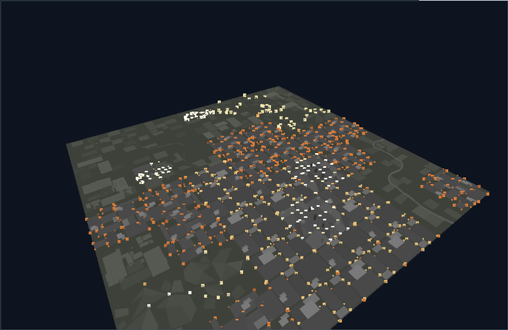
Terrain placement uses four exact quarter-turn transforms. For example, a 90-degree turn maps local (X,Z) to (Z,−X). It can do this by exchanging and negating coordinates, without looking up a sine. Moving aircraft and rotating parts use the more general matrix path we’ll reach shortly.
The ordinary native terrain neighbourhood is a 16 × 16 square around the camera’s anchor cell. The engine walks it in Z-major order and rejects assemblies outside the view using their bounding radii. The archive may hold a whole theatre, but the renderer works on a local neighbourhood.
The radius allows a cheap rejection before transforming every vertex. For a side-of-view test, the engine subtracts the radius from the magnitude of the camera-relative centre coordinate, projects that excess with the current focal length and compares it with the viewport extent. A centre outside the picture can still survive if part of its bounding volume reaches into view.
Geometry and weather are separate selections. A mission’s world chooses a regional grid such as yugoslav; its type chooses lighting and environment settings such as yugos_n. This caught us out during extraction because the archive also contains old grids with weather-like names. Loading one of those as the night-time map produced mountain slopes floating above roads. The game was loading a different grid all along.
Follow the implementation: terrain traversal, scene submission. Explore the recovered terrain and scenery.
The aircraft is a program
TFX’s 1,012 model resources describe much more than visible surfaces. A model can construct vertices, call a subroutine, turn a component, test a parameter, select a texture and choose which faces to draw first.
On disk, its instructions are big-endian 16-bit words. The loader converts the program in place. It changes byte order, turns opcodes into offsets for the drawing dispatch table, and turns vertex indices into byte offsets for 32-byte working records. The runtime therefore receives a program already prepared for its interpreter.
Some of its vocabulary is reassuringly direct:
| Instruction | Job |
|---|---|
| 1, 2, 3, 4 | Draw a line, triangle, quad or variable-length polygon. |
| 7, 8 | Jump or call a relative subroutine. |
| 21 | Branch on the facing of three projected vertices. |
| 32–37 | Compare a parameter byte and branch or call. |
| 71, 47 | Select a global texture and UV coordinates, then draw a textured polygon. |
| 72, 73 | Select a parameter; enter a rotated component. |
| 81 | Draw a carried model at an attachment point. |
| 82, 83 | Configure vertex jitter, then construct perturbed vertices. |
| 92, 93, 95, 96 | Draw sized circles, individually or in batches. |
| 97, 117 | Project a range of vertices, or one vertex. |
Vertices can be written as absolute coordinates or as deltas from a preceding position, including compact commands which change only one or two axes. A working vertex slot can be reused. Calls share drawing state and vertex records, so flattening the file into one immutable mesh loses part of its meaning.
The following is a sketch of the control flow, rather than the binary syntax:
construct the airframe vertices
project them
if this face points towards the camera:
    draw the far wing, fuselage and near wing
else:
    draw them in the opposite order

select parameter 0
choose the landing-gear pose
call the wheel drawing routine at its rotated anchor

draw each occupied weapon attachment
A model part has eight parameter bytes. Aircraft commonly use parameter 0 for gear and parameter 1 for doors or weapons bays. The same parameter 0 rotates a radar dish or raises a Scud missile on another model. Parameter 7 frequently selects damage and fire. These are inputs to a program, not eight globally defined animation tracks.
The surrounding scenery system supplies little animation streams which set, increment, decrement and loop those bytes. A landing gear sequence can therefore move through several poses; a bridge can switch directly to its destroyed state. Model drawing answers “what does state 12 look like?” The actor and scenery code decide when state 12 happens.
This also explains a particularly satisfying detail: missiles on a pylon are carried submodels, drawn at authored anchors with the aircraft’s current transform and scale. They are not separately positioned approximations floating beside the plane.
Choosing less to draw
The model header has distance thresholds and corresponding drawing entries. Close up, an entry runs a polygon program. Farther away, another can run simpler geometry, draw a two-by-two mark, draw a single pixel, or eventually supply no representation.
The distance used for this selection is a cheap approximation. Sort the absolute camera-space components so that a is the largest:
distance ≈ a + (b + c) / 4
It avoids a square root. Along an axis it is exact; along a three-dimensional diagonal it gives 1.5a, compared with the Euclidean √3a, about 1.732a. Its constant-distance contours are faceted rather than spherical. The renderer compares this quantity, after its fixed-point scaling, against the model’s own thresholds.
Detail levels can change the drawing technique as well as the number of polygons. A cloud may change from solid circles to checkerboard circles as it recedes. A distant aircraft becoming a dot is an explicit representation selected by the model header.
Inspect the Eurofighter, the Scud launcher or the ejecting pilot. Code: model interpreter, distance and sort keys.
From the wing to the camera
A point begins in model coordinates. TFX uses X for the lateral axis, negative Y for up and positive Z towards the aircraft’s nose. To place that point in the world, rotate it with the aircraft and add the aircraft’s position. To see it through the camera, subtract the camera’s position and rotate into the camera’s axes.
Written in ordinary linear-algebra notation:
Here R rotates the model, T is its location, C is the camera’s location, and V changes world axes into view axes. In camera space, positive Z is depth into the picture. An attached component contributes another local transform before this chain.

The original uses integer fixed-point arithmetic for these drawing operations. A rotation coefficient has fifteen fractional bits: a stored value near 32,767 represents approximately 1. Multiplying two such coefficients produces thirty fractional bits, so a right shift by fifteen brings the result back to the original scale.
Camera-space vertex coordinates carry sixteen fractional bits. This preserves sub-unit motion through the transforms, although projection later throws some of that precision away. A shift, a signed division and a stored 16-bit result each have their own rounding behaviour. Moving a rounding step to the end of a calculation can move an edge by a pixel.
A turn fits in sixteen bits
An angle wraps after 65,536 units. The rendering sine table has 1,024 entries, selected by shifting the angle right by six bits. Thus the matrix generators resolve roughly 0.352 degrees per table step. Cosine is the same lookup advanced by a quarter turn.
The samples follow trunc(32767 × sin(2πi / 1024)), with one small curiosity: the negative peak is −32,766 instead of −32,767. TFX and Inferno share that entry. It is a one-unit amplitude difference, separate from the much more visible quantisation of the angle itself.
The matrix generators use trigonometric sum-and-difference identities. Expressions involving sin(pitch + roll) and sin(pitch − roll) produce terms which a textbook implementation might calculate by multiplying sine and cosine. The exact sequence of halves, products and shifts is part of the result. The camera matrix and component matrix use different arrangements and rounding; swapping one for a conveniently inverted version of the other does not reproduce the same coefficients.
Scaling by moving the origin
There is another compact trick in the model language. Some commands scale the camera-relative translation while leaving the raw vertex coordinates alone. Perspective then makes the geometry appear larger or smaller relative to the model’s origin.
The F-117 uses translation factors of 80 for the airframe, 10 for a smoke helper and 4 for a fire helper. Relative to the airframe’s raw coordinates, the fire is effectively enlarged by 80 / 4 = 20. Our early viewer ignored this and hid tiny flames inside the fuselage. The program already contained a large fire; we had interpreted its coordinate system incorrectly.
Code: sine samples and matrix construction, model transforms.
Perspective, and the edge behind your head
Once a vertex is in camera space, perspective is a division. A point twice as far away has half the displacement from the centre of the image:
yscreen = cy + f · Y / Z
The ordinary TFX model projection has a focal length of 256 pixels. With Q16 camera coordinates, its integer path is:
depth = Z >> 16
screen_x = centre_x + (X >> 8) / depth
screen_y = centre_y + (Y >> 8) / depth
The division truncates towards zero. The projection centre comes from the active viewport, so it need not be the middle of the complete display. The missile-nose view changes the shifts and halves the model focal length to 128 pixels, giving a wider view.
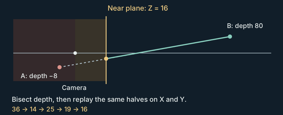
Objects crossing the camera need special treatment. Dividing by a depth close to zero sends their vertices across enormous distances on screen; a point behind the camera can even project to the opposite side. TFX flags model vertices at depth 16 or closer and clips crossing polygons against that near plane before filling them.
An intersection without the usual division
A conventional line-plane intersection calculates a fraction along the edge, then interpolates X and Y with it. TFX’s near-plane helper instead bisects the endpoint depths. It repeatedly takes their midpoint, keeps the half which contains depth 16, and records the choices in a bit word. It then replays those choices on the X and Y coordinates. Textured and shaded paths replay them on UVs or colour attributes too.
The depth search uses signed 16-bit whole depths. X and Y keep their fixed-point precision. This produces a very particular intersection, which an ordinary floating-point clipper need not round to the same pixel.
After projection, a separate clipper restricts the polygon to the screen rectangle. TFX visits bottom, top, right and left, adding an intersection whenever an edge enters or leaves a boundary. Its intersections use signed integer division and choose the farther endpoint for the calculation. These seemingly fussy choices decide which pixel an edge includes.
Inferno changes this part of the engine substantially. Its initial projector still marks vertices at depth 16, but the polygon clipping path can bring them forward to a near plane at depth 1. It reprojects with wider screen coordinates and clips against top, right, bottom and left. Lines retain the older depth-16 bisection path. The polygon and line versions therefore do not share one universal near plane.
One more inherited oddity: TFX’s distant-point projector uses a reciprocal multiplication instead of the model projector’s signed division. It also keeps the ordinary projection in missile-nose view while polygons use the wider one. Two representations of the same object can consequently disagree at a detail transition. This is one of the original inconsistencies we corrected in Redux.
Code: TFX near-plane bisection and point projection; Inferno geometry and clipping.
Who gets the last pixel?
Consider a box. From one side, its left face hides part of its right face; from the other, their relationship reverses. A depth buffer would settle each pixel individually. TFX instead has two levels of ordering.
Within a model, the drawing program supplies the sequence of faces. It can branch on the facing of three projected vertices, then call the appropriate sequence of drawing instructions. The basic test is a two-dimensional signed area:
area = (x1 − x0) * (y2 − y0)
     − (x2 − x0) * (y1 − y0)
Its sign tells which way those screen-space vertices wind. A branch can use that sign to choose a drawing order. The polygon rasteriser also has a winding rejection test of its own. A branch which chooses a sequence and a test which discards a face are separate decisions.
Between model parts, the engine uses a painter’s queue. Its key is the integer camera-space Z of the part’s origin plus a signed bias from its header. Larger keys draw first. Later, nearer parts overwrite their pixels.
This is cheaper than sorting every face against every other face. It also gives the artists a practical escape hatch when the origin of a large surface is a poor guide to its intended order.

sea1 and old carry a +3,000 bias, the rig has zero, and smoke_rg has −100. The drawing priority changes; the vertices stay in place.The queue holds 348 entries. Small batches use insertion sort. At fifteen entries or more, a quicksort partition pass precedes the insertion pass, and drawing walks the final list backwards. Equal keys inherit the original algorithm’s tie order. Replacing it with an arbitrary stable sort can change which of two overlapping parts wins.
Filling the queue triggers another sort, after which the slot belonging to the farthest entry is reused for the next submission. The eventual set of parts can therefore depend on submission order as well as distance. A larger draw distance cannot be obtained simply by visiting more cells while leaving every other limit unchanged.
A single depth key cannot solve every intersecting object. Nor can it repair a bad face sequence inside a model. We found a revealing example in bedford2: its cab sides draw before the flat-bed top, but its windscreen and roof draw afterwards. In the model viewer, the bed can cover the sides while leaving the glass and roof visible. Reading the instruction order explains that oddly selective overlap.
The same design makes ground overlays straightforward. A blast scar is a textured polygon at ground level, drawn over the ground. It does not need a tiny geometric offset to appease a depth buffer. When we moved those surfaces into a WebGL inspection viewer, coplanar depth fighting became our problem to solve.
Code: the bounded queue and original sorting order. Model data and face sequences: full model workbench.
Turning a polygon into spans
After transforms, ordering, facing and clipping, the renderer finally has a polygon in screen coordinates. It still needs to decide which pixels lie inside it.
TFX’s ordinary polygon path finds the topmost and bottommost vertices, then walks the boundary in both directions from the top. Each boundary becomes a chain of edges. One walker supplies the left X position for a row; the other supplies the right X position. The pixels between them form a span.
For an edge of height h and horizontal displacement dx, the ideal per-row step is dx / h. TFX constructs its Q16 step using a Q15 reciprocal:
reciprocal(h) = floor(32768 / h)   // 32767 for h = 1
step_q16 = dx * 2 * reciprocal(h)
x_q16 += step_q16                 // advance one screen row
The two factors of 32,768 supply the familiar 65,536 fixed-point scale. The edge starts with a half-unit rounding bias; sufficiently steep changes add half a step as well. At a vertex, the walker installs the next edge’s start and increment.
The supported outline needs to split into two chains which move down the screen. This is not a general concave-polygon tessellator. The native model language’s polygon command is not a promise that an arbitrary outline will be triangulated for you.
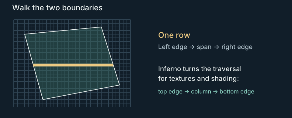
The TFX edge pass produces top-to-bottom spans, but the VGA writer consumes them bottom first. Endpoints are inclusive. An edge rounding differently by one unit changes a whole run of pixels, and a span that crosses itself can terminate a native drawing batch. That is why a modern triangle rasteriser with its own shared-edge rules can look close without matching the original.
Flat spans have the cheapest inner loop: write the same index repeatedly. Shaded spans carry another value at each edge and step it across the row. Textured spans carry two. The edge machinery is doing the interpolation work before the innermost pixel loop begins.
Rounding a corner without adding a mesh
There are specialised rounded primitives too. For a rounded quad, TFX projects the four edge midpoints, fills the central quad they form, then adds a small curved section around each original corner. The midpoints are found in camera space before projection, so they need not land halfway between the projected endpoints.
The corner generator uses a fixed-point recurrence. After setting up two accumulators from the corner and its neighbours, the central update is:
b -= a >> subdivision
a += b >> subdivision
Each update supplies another point on the arc. Rounded quad corners use eight points; the standalone three-vertex curve uses fourteen. The additions and shifts generate the curve without a fresh sine or cosine lookup for every point. Its outline then goes through the ordinary span machinery.
Inferno keeps horizontal spans for ordinary flat polygons, but its textured and shaded paths build vertical columns. They walk from maximum X towards minimum X, push column records, and consume them from left to right. This is a real algorithmic change within an otherwise very recognisable engine.
Code: TFX edge walkers and span writers, Inferno column writers.
A texture is another set of indices
TFX uses a small amount of texture mapping among its flat and shaded surfaces. A raw .tm page is 256 × 192 bytes, without a palette or a header. The address of a texel is simply:
address = v * 256 + u
Global texture slots let many models refer to the same pages. Aircraft markings, cockpit instruments, flare artwork and ground scars can occupy different rectangles of an atlas. The damaged tripipe model, for example, selects four UV corners around the blast-scar artwork in global_1.tm and draws a quad on the ground.
UV coordinates acquire seven fractional bits during model conversion. They are interpolated along the screen-space edges and then across each span. The pixel writer takes the integer texel position and fetches one byte. There is no bilinear filtering.
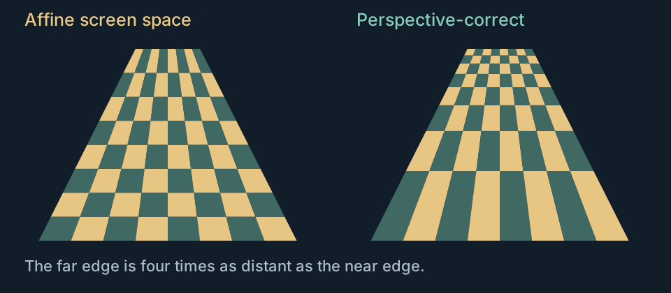
This mapping is affine in screen space. If the left end of a span has U = 0 and the right end has U = 100, the screen midpoint receives U ≈ 50, whatever the endpoints’ depths.
A perspective-correct mapper instead interpolates u/z, v/z and 1/z, then divides to recover U and V at the pixel. That division changes the spacing along a surface which recedes from the camera. TFX avoids it. The resulting stretch is most apparent on large, oblique textured faces.
The texel’s index is then passed through a colour-remapping table. In TFX, the remapped value decides transparency. If it is zero, the pixel is left alone. A nonzero source texel can therefore disappear if the remap turns it into zero; a source zero can paint if remapped to another index.
Inferno tests the source texel for zero instead. A nonzero texel remapped to zero draws black there. This is a tiny change in the inner loop with a visible consequence around transparent artwork.
Code: texture attributes and near clipping, affine sampling. Explore the original texture bindings.
Colour does some of the geometry’s work
A smoothly shaded polygon normally suggests RGB values being blended across its surface. TFX’s Gouraud shading interpolates palette indices. Its per-vertex shade attributes are 8.8 fixed-point values. Interpolation chooses intermediate entries in the palette, followed by the selected remap.
For that to look like a smooth material, the palette entries need to form a useful ramp. If the consecutive entries run from dark grey to light grey, the surface looks shaded. If they alternate between unrelated colours, the exact same interpolation becomes a rainbow. The palette is part of the artwork’s construction.
Separate from the 256-colour VGA palette is coltab.dat: sixteen rows of 256 output indices. This is a 4,096-byte lookup table, not sixteen RGB palettes. Given a row and a source index, the renderer gets a replacement index. TFX’s ordinary distance-colour helper selects a row by shifting camera depth right by nine whole units and clamping to 0–15. Model instructions can also request colour selection using face depth.
An index can thus go through several distinct stages:
or texture index→Remap row
another index→VGA palette
red, green, blue
The environment supplies several palette banks. TFX blends five banks according to altitude, in integer steps, while protecting entries needed for instruments and other special colours. Night vision and infrared views select another palette. Blackout, redout and flashes also alter the palette output.
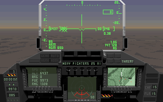 Normal view
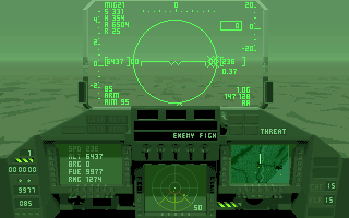 Night vision
Night lights take another route. City and runway model programs test a global night flag, then draw their authored small marks in amber or pale yellow. They are visible points, rather than light sources which illuminate neighbouring geometry. Their arrangement along streets and runway edges supplies most of the effect.
Inferno makes extensive use of environment-specific palettes: orbital planets, the sun, Federation and Rexxon interiors, rings and underwater scenery all have appropriate bindings. That is why the palette called standard was such a poor default for our model browser. The name did not make it a universal material palette.
Its model language adds a depth-shading wrapper, opcode 122, which interpolates remap-row values across a polygon. A large face can then change its colour treatment with depth instead of choosing one row for the whole face. Opcode 118 supplies the related per-face distance-colour mode, already present in the shared instruction family.
Code: index remapping, environment palette updates. Browse the palettes and raster patterns.
Smoke with holes, clouds made of circles
TFX can draw both fixed-size pixel effects and circles with a radius supplied by the model. These are different primitives. A small city light and a large smoke particle should not be given the same size just because both originate at a vertex.
The sized-circle projection uses:
screen_radius = trunc(size_operand * 128 / camera_depth)
The ordinary point projection has a focal length of 256, so the stored size operand does not map one-for-one to a geometric radius under that projection. TFX’s circle-row tables contain the extents produced by an integer midpoint-circle construction. Starting in one octant, it advances along X and uses an error accumulator to decide when to reduce Y; symmetry supplies the other octants. The resulting row extents become spans for the same flat or patterned painters. Inferno also has explicit tiny-size cases and an integer circle recurrence.
The cloud1 through cloud4 models each draw fifteen overlapping circles. Their closer detail programs use solid colours. The next versions use half-coverage checkerboards and quarter-coverage dots. The cooling tower cltwr2 uses checkerboard steam even in its single polygon detail program.
These are screen-door patterns: chosen pixels receive the smoke colour and the holes retain the background. No RGB alpha calculation is involved. The pattern aligns to screen coordinates, so overlapping identical patterns leave the same holes. Two overlapping half-coverage circles do not automatically become three-quarter opaque.
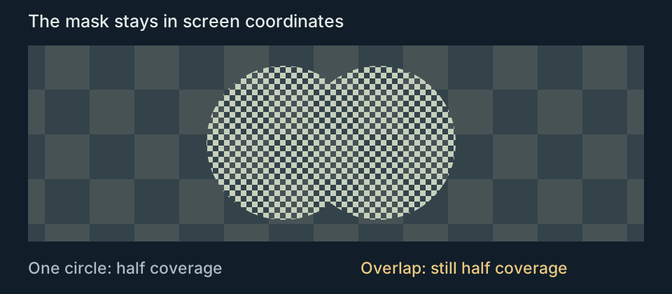
The engine also has sparse patterns, horizontal stripes and procedural stipple. Other modes apply XOR, AND or OR to source and destination index bytes. The result goes through the palette like any other index; these operations are not equivalents of modern additive or multiplicative RGB blending.
Motion comes from another small mechanism. Vertex-jitter commands update a pair of 16-bit random-state words with addition and carry, then keep a signed portion of the result as a displacement. A shift of 14 gives offsets from −2 to +1; a shift of 13 gives −4 to +3. The displacement is applied before component rotation.
Fire can therefore combine a parameter-controlled sequence with perturbed vertices. A smoke stage can hold its selected geometry while its vertices continue to move. The pilot’s parachute uses the same family of vertex motion. Frame setup saves and restores the jitter seed around the animation pulse, keeping intervening renders from inventing a fresh shape on every draw.
Inferno retains these circle and pattern mechanisms, and adds another expensive-looking effect by an entirely different route: its scaled sprite renderer generates x86 load/store instructions for the requested resize, then executes the generated loop. An explosion sprite is prepared as a specialised blitter for its current dimensions.
Code: pixel patterns, vertex jitter. Try the cloud model and cooling tower.
Painting the horizon before the hills
A theatre does not need to extend to infinity to fill the bottom of the picture. Before drawing the local world, TFX paints a horizon made from broad palette-coloured strips.
The horizon builder uses camera pitch and roll to project a set of height/depth pairs. It extends those projected boundaries across the viewport to form bands. Near a steep roll it switches which screen axis it uses to build them. Sky bands begin around palette index 240; ground bands begin around 224. A movement phase shifts the ground pattern as the aircraft travels.
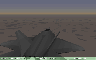
Those bands supply a background under the finite terrain neighbourhood. The local scenery can leave areas uncovered without revealing an empty framebuffer. Palette selection helps the foreground surfaces and background converge in colour at a distance.
Ground shadows also avoid an expensive general solution. The model transform can flatten the aircraft onto an XZ plane before applying the view transform, and the shadow path paints its silhouette. There is no shadow map and no light-to-surface visibility pass. The ordinary placement helper only supplies this shadow close to the ground.
Inferno uses the shared world machinery for a broader collection of environments. It can select another terrain layer with altitude, draw orbital planet backdrops and change palettes around rings or underwater regions. Its interiors are assembled scenery too. A room flag selects appropriate walls and connecting parts; navigation and collision use a separate library of tubes and room volumes. A visible corridor and the volume through which a ship can fly are related pieces of data, not the same polygon mesh.
Code: horizon bands, shadow placement. Explore Inferno’s worlds and corridors.
Writing into VGA memory
The picture is logically a 320 × 200 array, but the VGA drawing surface is divided across four planes. Adjacent pixels go to successive planes:
plane   = x & 3
address = page_base + y * 80 + (x >> 2)
Each plane holds every fourth pixel of a row. A map mask chooses which planes a write affects. For a flat span, an interior write can put the same byte into all four planes, painting four adjacent pixels at once. The two ends need masks to select only the covered pixels.

This layout explains details which look peculiar in isolation. Pattern density can be expressed with plane masks. Some sparse painters count VGA byte groups rather than individual pixels. The native flat-span writer uses an unrolled jump table, while the Gouraud path rearranges its fractional accumulator and propagates the processor’s carry between pixels. These routines are built around the display memory they have to feed.
TFX rotates through three retained VGA pages. It draws one while another is displayed, then changes the displayed page. Pixels outside a painter’s coverage remain in that page until something overwrites them. Static cockpit panels need copying to all three pages after a layout change; the engine has a refresh count for precisely that purpose.
The cockpit is partly executable artwork
Some cockpit overlay resources contain actual x86 drawing programs. Calling one with a destination page and offsets paints the canopy or frame directly into the VGA planes. Other parts are raw planar bitmaps. Live instruments combine sprite banks, embedded font glyphs, lines and numbers.
An untouched pixel in a compiled overlay is transparent because the code never writes it. A deliberately written black pixel is opaque. Treating every black pixel as a transparency key cuts holes in the cockpit.
The virtual cockpit follows the model route: transformed polygons and textured instrument panels. Its MFD images in the original TFX are static artwork. The live radar, map and camera displays are drawn by the fixed cockpit’s instrument routines. We initially expected the virtual panels to update, but the game itself showed the same fixed pictures. Live virtual instruments are a Redux addition.
A camera MFD is a more involved display than a bitmap gauge. It sets up another view, paints a world through a small viewport, then returns to the cockpit composition. Those extra camera passes have to coexist with the shared renderer’s transforms, parameters and random state. Following the order of calls matters just as much as recovering the polygon filler.
Code: retained pages, cockpit composition. Compare the cockpit layers.
What Inferno adds
By the time we opened Inferno and its 1,691 model programs, the family resemblance was immediately useful. Model commands, scenery programs, quarter-turn placement, fixed-point transforms, palette tables and patterned circles all gave us familiar starting points. Then the differences began to show up in pixels.
| Mechanism | TFX 2.05 | Inferno CD 1.58 |
|---|---|---|
| Model language | Drawing programs with branches, components and parameter bytes. | Retains the layouts through opcode 120; adds 121 and 122. |
| Flat polygons | Horizontal spans. | Horizontal spans. |
| Textures and interpolated shading | Horizontal spans, consumed bottom first. | Vertical columns, consumed left to right. |
| Near clipping | Depth-16 bisection path. | Depth-1 polygon path; depth-16 line path. |
| Texture transparency | Test the remapped index for zero. | Test the source texel for zero. |
| Depth colour | Object/face-selected index remaps. | Also interpolates remap rows over a face with opcode 122. |
| Object ordering | 348-entry painter queue and per-model face order. | Same queue capacity and two levels of ordering. |
| Worlds | Regional terrain, weather, cloud layers and sky objects. | Also orbital backdrops, rings, underwater environments and interiors. |
Opcode 121 is an especially neat addition. It calls a subprogram while collecting the edges of its front-facing flat polygons. Projected endpoints are put into a canonical order, so a shared edge is recognised whichever direction a face traverses it. Edges seen twice are suppressed; edges seen only once are drawn in the requested outline colour.
This produces a boundary without drawing every internal polygon seam. The collector has a fixed buffer of 399 distinct edges. It is another example of using the model program to select a rendering operation rather than building a separate mesh just for that effect.
The two games also make a good demonstration of why reusing a decoder is easier than reusing an exact renderer. An Inferno model may parse perfectly with almost all of TFX’s instruction layouts, yet its textures, clipped edges and outlines still need different drawing routines.
Code: Inferno’s model wrappers and outline collector. Browse Inferno Investigated for the companion project.
Following the code all the way down
A convincing aircraft is a useful first milestone. It is a poor test of a renderer’s last few details. A wrong rounding rule can hide in a large face and become obvious only on a thin wing. A texture can look plausible until a lighting remap turns one of its indices into zero. A queue can appear sorted correctly until several parts have the same key.
We used the original executables as callable reference implementations. A harness supplies a routine with coordinates, state and resource bindings, executes its machine instructions, and records the result. For drawing tests it captures the VGA planes and reconstructs the indexed framebuffer. The C++ implementation receives the same inputs, and we compare the indices and state.
That lets us ask focused questions. Which endpoint does a clipper interpolate from? Does this span include the final pixel? Does a zero texel disappear before or after remapping? Does a component restore its selected parameter when it returns? Each question has a small input and a concrete output, and we can then carry the answer into complete model and flight captures.
The result is an engine whose character comes from choices at every scale. The landscape is assembled from local programs. Aircraft carry their own drawing decisions. Palette ramps do shading work. A circle with a patterned mask becomes a cloud, and a group of four VGA planes shapes the innermost loops.
Next time the runway lights slide underneath the cockpit, there is a lot to look for in those 64,000 pixels.
Keep exploring
- How TFX’s weapons work: missile guidance, bomb trajectories, damage and countermeasures.
- How TFX flies: lift, controls, engines and landings inside the flight model.
- Open the model gallery and try the parameters, detail levels and palettes.
- Explore the five theatres and their assembled scenery.
- Read the full TFX research, or follow the reconstructed routines in TFX C++ and Inferno C++.
- For another engine, Fabien Sanglard’s Build engine internals is a wonderful tour, and an inspiration for this article.